gbg-pcb
Instructions for using the GBG-PCB to make a go baby go car
questions? post here or email gobabygocarswithjoysticks@gmail.com
Instructions for specific models of cars
Parts needed
- a car
- materials for frame and backrest (usually pvc pipe)
- materials for modifying the car to spin in place (caster wheels)
- joystick (recommended part: Radiolink joystick replacement for RC controllers AT9 and AT10 (get the “back to middle” type that springs back on both axes) )
- four wire electrical cable - for joystick
- 3D printed parts (handles, joystick holder)
- an assembled joystickpcb
- an assembled GBG-PCB
v1.1 and v1.2 boards are interchangeable - they use different heatsinks as component availability changed.
- Feel free to use these files and make your own boards or modify this design. The components cost approximately $50 but it really depends on what quantity of boards you are making and what shipping costs you have to pay.
- Email gobabygocarswithjoysticks@gmail.com. I might have assembled boards to sell or donate to you. I’ll include a joystick pcb with any GBG-PCBs I give out. Boards currently in-stock: 2
- Use this PCBWay link to order fully assembled boards. Thank you to PCBWay for supporting this project. (As of May 2025 this link has not been tested - I haven’t ordered any assembled boards). When ordering assembled PCBs, you may be asked by PCBWay whether you want a Pico 1 or Pico 1W. Specify the 1W if you want wifi remote capability, or clarify that you want the Pico 1 if you don’t need a remote and want to save a couple dollars.
Tools needed
- small flathead screwdriver (3mm)
- large flathead screwdriver (6mm)
- small Phillips screwdriver (2.0)
- wire strippers
- wire cutters
- micro USB cable
Circuit diagram
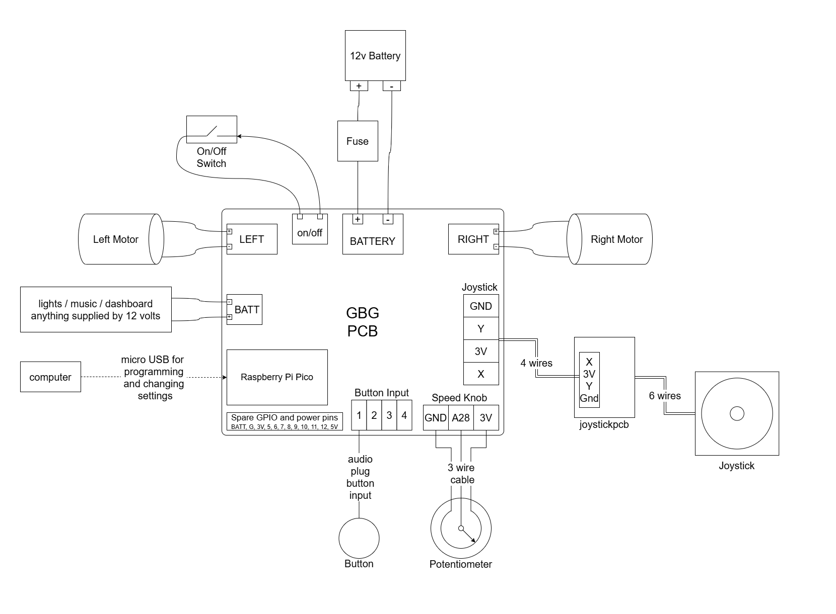
Schematic of GBG-PCB
List Of Components to build a GBG-PCB
New in V2: Weelye control box compatible
Ride on cars frequently come with a control box labeled “weelye.” The GBG-PCB can be configured with plugs that match the weelye box so that some models of cars can be modified without cutting any wires.
The plug carrying signal wires to the box can be plugged into J11 with the usually-red wire plugged into the pin labeled bat+ and if the plug from the car has fewer than 10 sockets leave the rightmost pins of the PCB unused.
A GBG-PCB can be assembled with alternate motor and battery connectors that are compatible with the plugs on weelye boxes. See section titled “alternate battery and motor connectors weelye mode” for what components to change.
Choose a Car
6 to 24 volts
While V1 boards required 12 volts, V2 GBG-PCBs can be used with 6 volt, 12 volt, or 24 volt cars.
Two motors
The car will be steered by controlling the two back wheels separately, so the car needs to have a motor for each wheel.
Cars with two speeds often have two motors in them.
Some cars are sold with one motor but have space in the frame to add a second motor.
Able to (be modified to) spin in place
Some models already can spin in place (“bumper cars”)
For most cars, you’ll need to remove the front wheels and add swivelling caster wheels.
Fits a frame and has a way to connect a joystick
Go Baby Go cars usually get a PVC pipe frame with a backrest
It’s easier to fit a frame to a blockier car with more right angles
The joystick can be connected to the frame, or it can be put on the end of an “adjustable photo arm”
Here are some 3D printed parts that could be used to hold the joystick.
Disconnect the battery
If possible, disconnect one wire from the battery to keep the circuit off while you are working on it. Some cars have a spade terminal that comes disconnected from the battery of a new car.
Wire the PCB to the motors
Find the motors
The motors are usually under the seat of the car
Prepare the motor wires
Cut the plugs off the ends of the motor wires
Strip the insulation off the ends of the wires
Connect the motors to the PCB
The motors can be reversed or swapped left/right in software later.
Wire the PCB to the battery
If there is a plug that comes from the battery and goes to a circuit board that is already in the car, you can probably cut that plug off and use those wires to power the GBG-PCB.
If you see a fuse (usually a small black box with two wires coming out of it), please leave it in the circuit between the battery and the GBG-PCB. It’s a really good idea to have a fuse between the battery and the PCB; if you need to get a fuse, a 10 Amp auto resetting fuse is a reasonable choice.
Connect the positive battery wire (usually red) to the positive BATTERY terminal on the GBG-PCB (labeled “+”).
Connect the negative battery wire (usually black) to the negative BATTERY terminal on the GBG-PCB (labeled “-“).
The GBG-PCB has reverse voltage protection, so it won’t be damaged if you accidentally connect the battery backwards. It just won’t turn on.
The PCB can be left connected to the battery. It does not need a switch between itself and the battery. The PCB has MOSFETs that stop electricity from flowing when the on/off switch is off. When the PCB is off it draws practically zero current (2 nanoAmps) so it will not make the battery discharge.
If your car has a switch that can handle the full current of the car, you can use that switch as the main power on/off switch and put it between the battery and the GBG-PCB. If you do this, connect the two terminals labeled “on/off” on the GBG-PCB together with a short wire.
Wire the PCB to the on/off switch
Choose or add a switch to use as the main power on/off switch.
Low currents (about 4 mA) will flow through this circuit, so any wires and switches will work.
Connect the switch to the screw terminal labeled on/off.
Current can flow either way through a switch so either wire from the switch can go to either terminal.
An electrical connection between the two terminals of the on/off screw terminal block will turn the PCB on.
It doesn’t matter for a switch (and I recommend just using a regular switch), but in case you’re interested, the terminal closer to the battery is connected to the positive wire of the battery and the terminal closer to the left motor should be pulled to 12 Volts to turn the board on. The MOSFETs interrupt the connection to the negative wire of the battery. The instructions specifically for the jeep describe how to use the button on the dashboard to turn the car on, and in that case the dashboard needs to be grounded directly to the battery or the signal from the button on the dashboard floats high and the car can’t be turned off. The instructions specifically for the zupapa bumper car describe how to add the GBG-PCB in parallel to the existing control box and that strategy is helpful for cars with more complex wiring for the battery charger.
Wire the Joystick
 Use a 4 wire cable to connect the GBG-PCB to the joystickpcb.
This picture shows the circuit but for illustration purposes the wires are very short. The wires should be long enough to reach from the PCB to wherever the joystick will be placed on the car and the wires should be long enough to be routed through the frame of the car.
(optional) Wire Buttons and/or Speed Knob
Buttons
Plug up to 4 buttons into the headphone-style jacks on the GBG-PCB.
When you connect the GBG-PCB to your computer to change the settings, click the “show all” button and check the box next to “enable button_ctrl”. Then, you can set what direction each button should make the car move in.
Speed Knob
You can add a knob to the car for easily adjusting the maximum speed of the car without needing to reprogram it.
Connect a potentiometer to the screw terminal labeled “speed knob”. When you connect the GBG-PCB to your computer to change the settings, click the “show all” button and check the box next to “use speed knob”.
Program the Pico
Flash the firmware to the Pico
If you got your GBG-PCB from someone who already programmed it for you, then you can skip ahead to calibrating the joystick and adjusting settings.
Go to the go baby go programmer website and follow the instructions to upload code to a new car.
Select the PCB_gbg_program. If you don’t see the PCB program, click on Advanced settings and check the box to get car code from the main branch.
Connect
Connect the GBG-PCB to your computer with a micro USB cable
Go to the go baby go programmer website
Follow the instructions pointed to with the magenta arrow to connect to the car
Calibrate the joystick and adjust settings
Click the “calibrate the joystick the easy way” button and follow the instructions on the screen
You can also adjust the speed and acceleration settings for the car.
Reconnect the battery
If you disconnected a wire from the battery (or the car comes with a wire disconnected for shipping), reconnect it now.
Test the car
disconnect the car from the computer
turn on the car using the on/off switch
the three green lights on the PCB should turn on
you should hear a short beep from the motors
the car should drive when you move the joystick
the blue light on the PCB should turn on when the car is moving and turn off when the joystick is centered
if the blue light blinks quickly that means the joystick needs to be left centered for a few seconds before trying to move and that the joystick may need to be recalibrated
Notes on remote control
See this page for several methods of remote control: remote control
Over wifi
This feature is available on GBG-PCBs with a Pico 1W or 2W.
Check the “use wifi” setting on the programmer website, then follow the instructions and QR codes on the programmer website.
The Pico will create a wifi network and will serve a webpage that allows you to control the car and change settings of the car.
The wifi range is unreliable (sometimes measured as 10 feet sometimes as 100 feet).
For more information, see the remote control page linked above.