gbg-pcb
questions? post here or email gobabygocarswithjoysticks@gmail.com
Parts needed
- an Aosom jeep (Aosom SKU: 370-038, I also see an identical looking car on costzon.com)
- 2x 5” caster w/ 1/2”-13 x 1-1/2” threaded stem and “No Brake” option
- 4x washer with 1/2” inner diameter
- 2x 1/2”-13 lock nuts
- Radiolink joystick replacement for RC controllers AT9 and AT10 (get the “back to middle” type that springs back on both axes)
- 4.5’ length of four-wire ribbon cable
- 2x 4-40 nut
- 2x 4-40 1.25 inch machine screw with phillips head
- 12” of 1/4 split loom plastic wire protector tube
- 18x m2.2x14mm screws
- 10 foot length of 3/4 inch schedule 40 PVC tubing
- 2x 1/4-20 locknut
- 2x 1/4-20 3/4 inch machine screw with rounded head
- 8x 3/4 inch PVC pipe 90 degree elbows
- 4x 2 inch long #6 wood screws (for attaching the frame to the car)
- 4x plywood chunks (about 1 inch by 1.5 inches by 2 inches)
- 3/4” x 1 3/4” piece of 1/16” rubber gasket sheet
- 2x large zip ties
-
harness or seatbelt or velcro or foam kickboard (any supplies needed to make a backrest and provide enough support for the child to sit in the car. the harnesses we used to use are out of stock)
- 3D printed parts (3 handles, 3 joystick holder components, 2 pairs of pvc tee parts)
- an assembled joystickpcb (I’ll include these with any GBG-PCBs that I give out)
- an assembled GBG-PCB
v1.1 and v1.2 boards are interchangeable - they use different heatsinks as component availability changed.
- Feel free to use these files and make your own boards or modify this design. The components cost approximately $50 but it really depends on what quantity of boards you are making and what shipping costs you have to pay.
- Email gobabygocarswithjoysticks@gmail.com. I might have assembled boards to sell or donate to you. I’ll include a joystick pcb with any GBG-PCBs I give out. Boards currently in-stock: 2
- Use this PCBWay link to order fully assembled boards. Thank you to PCBWay for supporting this project. (As of May 2025 this link has not been tested - I haven’t ordered any assembled boards). When ordering assembled PCBs, you may be asked by PCBWay whether you want a Pico 1 or Pico 1W. Specify the 1W if you want wifi remote capability, or clarify that you want the Pico 1 if you don’t need a remote and want to save a couple dollars.
Tools needed
- small flathead screwdriver (3mm)
- flathead screwdriver (larger)
- small phillips head screwdriver (2.0)
- phillips head screwdriver bit for a drill or electric screwdriver
- screwdriver bit for a drill or electric screwdriver that fits the wood screws
- wire strippers
- wire cutters
- micro USB cable
- box cutter
- clamps
- rotary tool (Dremel) with cutting wheel
- hammer
- pvc glue
- T6 Torx screwdriver
- duct tape that matches the color of the car
- permanent marker (or label maker)
- hot glue
- drill
- 1/16” drill bit (for drilling holes in the 3D printed parts)
- 5/64” drill bit (for drilling pilot holes for the wood screws for the frame)
- 3/32” drill bit (for drilling out the holes in the joystick handles)
- adjustable wrench (at least 3/4 inches wide)
- channel lock pliers
- 3D printer access
- Computer with internet access and a usb port
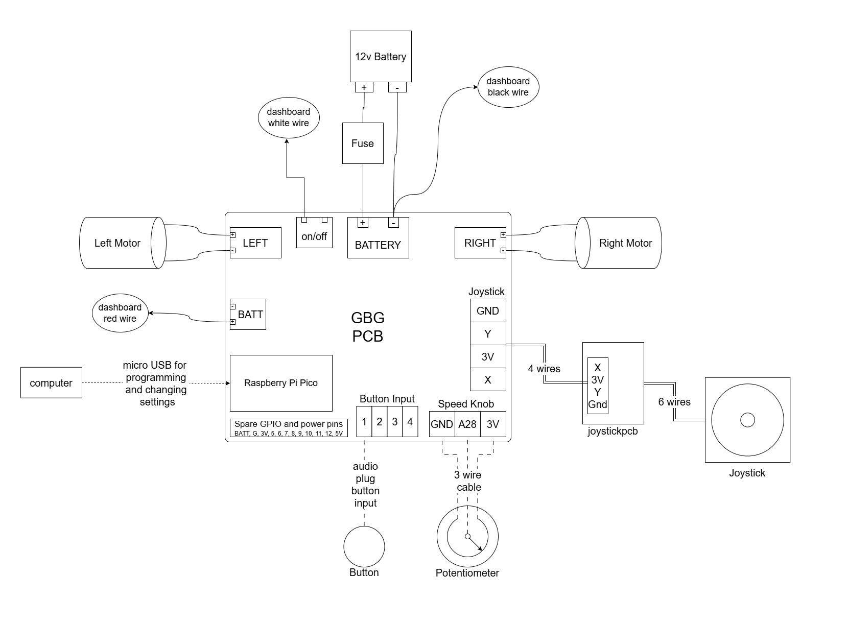
Circuit diagram
PCB Schematic
PCB List Of Components
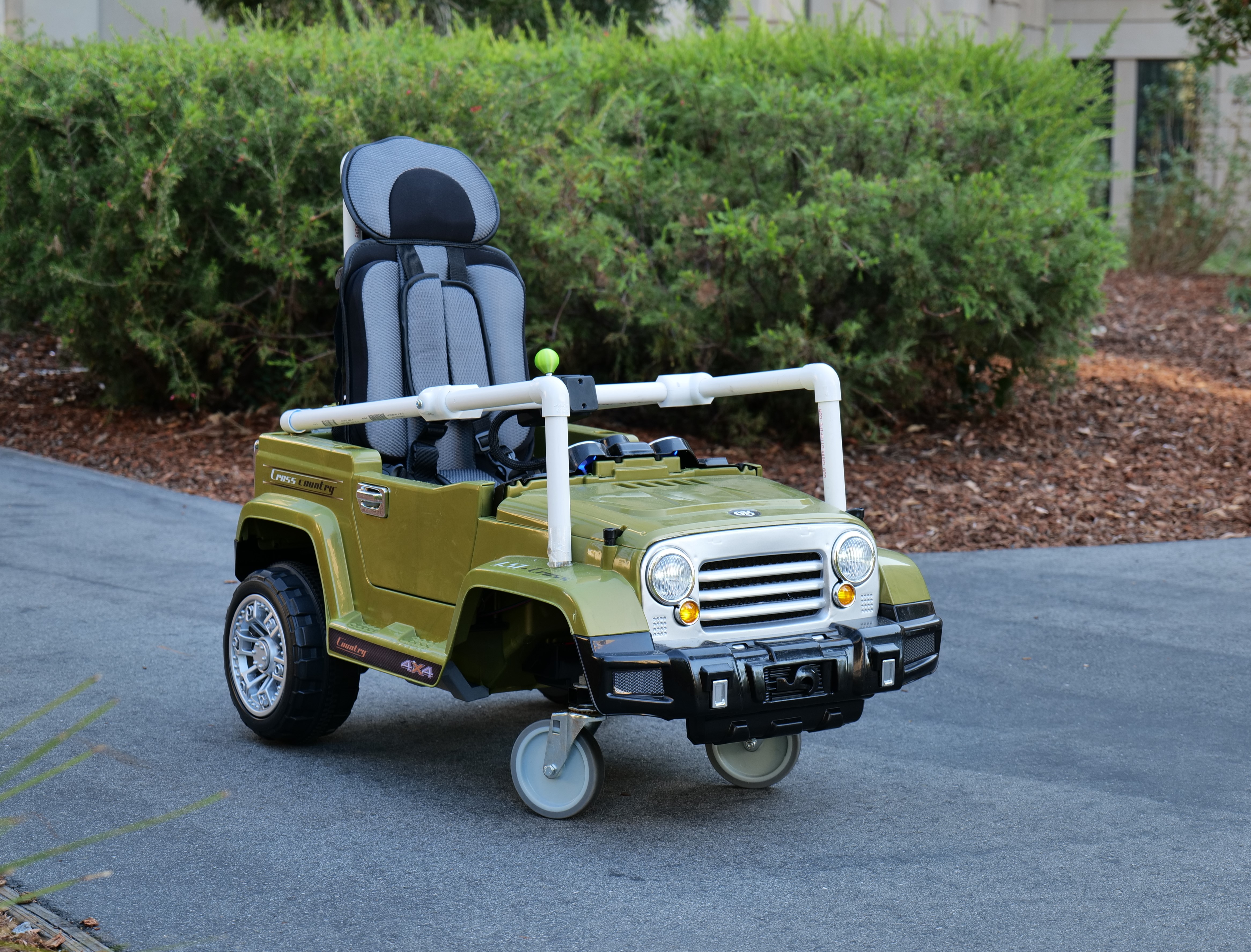
note: some photos are of a white Jeep, some are of a green Jeep. Please just ignore the color changes, the two cars are otherwise identical.
Unpack the Jeep (Parts to Keep)
201: Back wheels
202: Back axle (attached to steering mechanism)
203: Front bar (attached to steering mechanism)
204: Grey reinforcement pieces
205: Seat
206: Little plastic wrenches
207: Bags of nuts, bolts, and screws
208: Back motors
209: Motor covers
210: Charger
211: Driving lights
212: Toolbox
213: Auxiliary cord for music
214: Manual
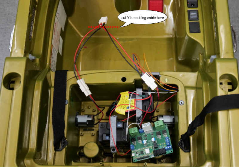
not pictured: Y branching motor cable that comes connected to the control box
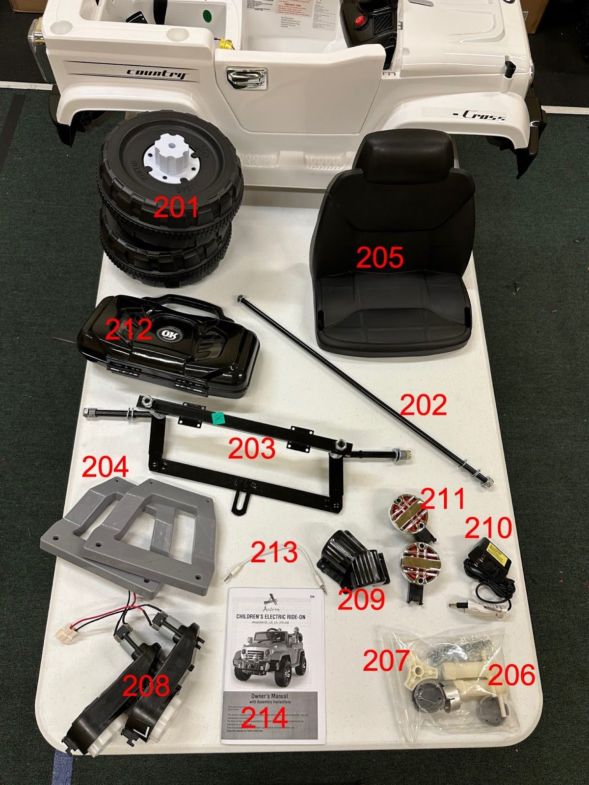
Left over parts of the Jeep can be discarded.
Frame and Wheel Modifications
Back wheels
Remove all nuts and washers from the back axle.
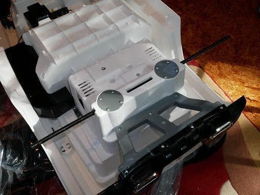
Slide the back axle into place as shown below.
Put the two back motors on the back axle. Make sure to check the labels on the motors that say L or R and put the L motor on the side of the car that will be on the left side when the car is upright from the perspective of the driver, and put the R motor on the right side of the car. If the motors are on the wrong sides the car will drive backwards.
Install back motors, back wheels, washers, nuts (tighten the nuts on the two ends of the axle, simultaneously), and hubcaps as shown in the manual (image below). Use the provided plastic wrenches.
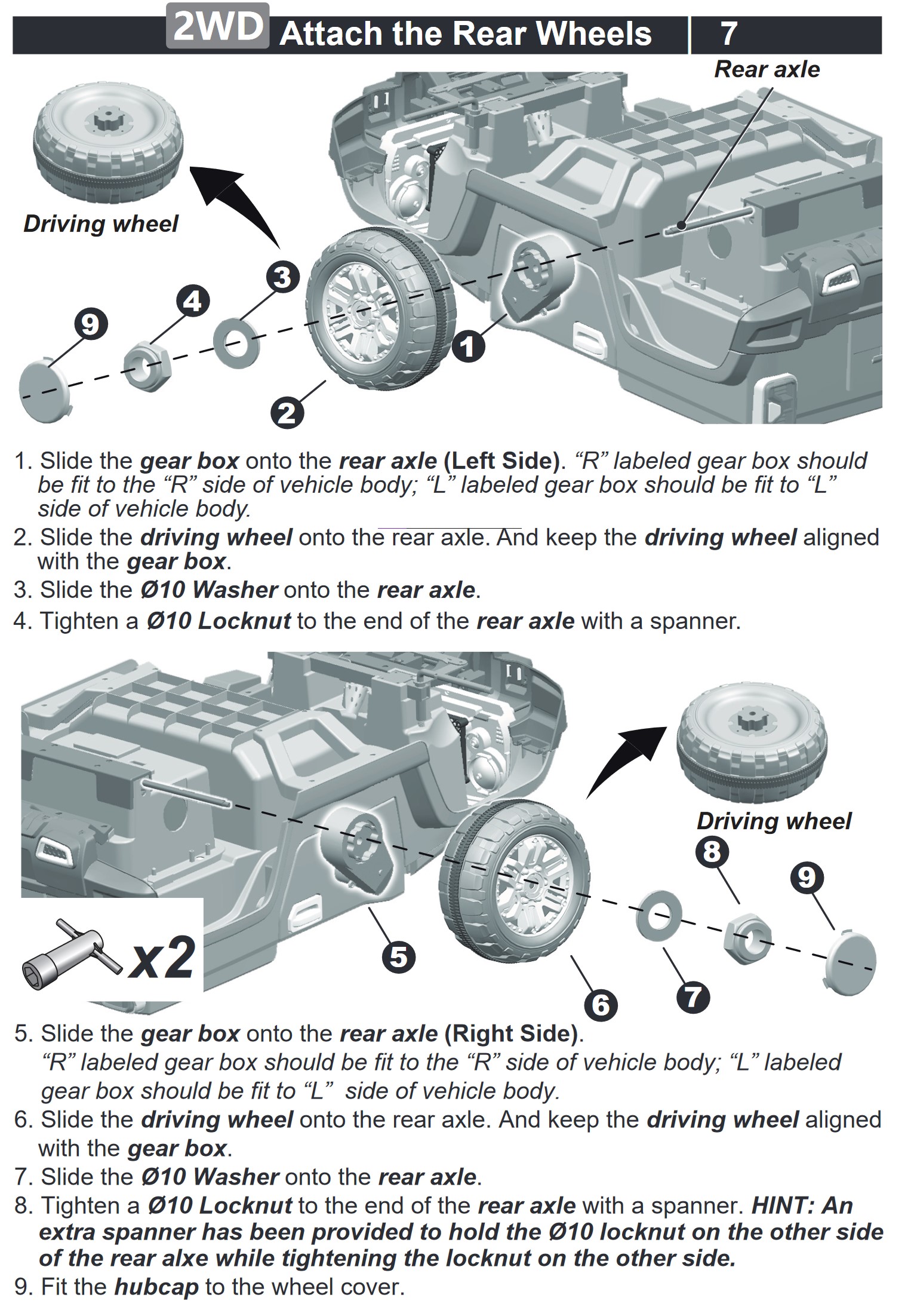
Check to make sure that the back wheels spin freely. If they don’t, loosen the nuts a little bit.
Front Caster Wheels
The front steering motor will not be used. The motor is on the underside of the car. Unplug the wires to the motor. Unscrew the motor, remove and discard.
Unscrew the locknuts from the metal steering mechanism to remove the front bar and use a clamp to securely hold the front bar for cutting the welds on it, in the next step.
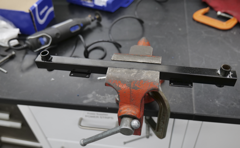
Remove the round tubes on the front bar by using the rotary tool and a cutting wheel to cut through the welds that hold the tubes in place. (Try to maintain the structural integrity of the square bar while cutting; the round tubes will be disposed of, so damaging them while cutting is acceptable.) After the welds are cut, use a hammer to tap the tubes out (make sure to hammer from the side of the tube OPPOSITE the weld).
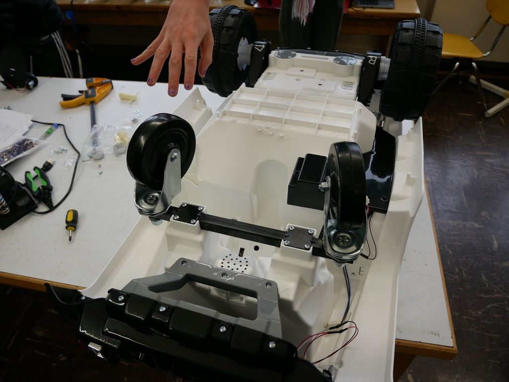
Place the casters into the holes in the bar (where the tubes were), with washers on both sides of the hole. Bolt the casters to the bar using ½-13 lock nuts, using large channel lock pliers to keep the caster from spinning while turning the nut with a ¾” wrench. Make sure that the casters are not installed upside-down; mounting tabs on the bar should be on the wheel side.
Use screws found in the Jeep parts to screw the front bar to the Jeep.
PVC Frame
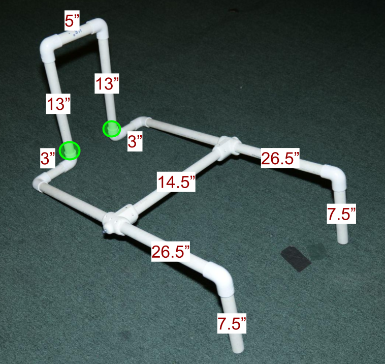
Cut the 10 foot length of 3/4 inch PVC pipe to the following lengths, as also shown in the diagram below:
- 2x 26.5” pieces
- 1x 14.5” piece
- 2x 13” pieces
- 2x 7.5” pieces
- 1x 5” piece
- 2x 3” pieces
Join the two parts of each 3D printed saddle tee together, using five m2.2x14mm screws.
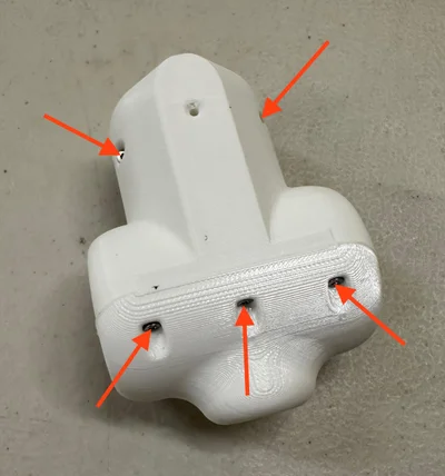
Place a ¼-20 locknut into the pocket at the end of each connector tee, then screw a ¼-20 ¾” machine screw with rounded head through the hole at the side of the tee and into the nut, just enough to hold the nut in place. (the nuts and bolts can also be added later, after the frame is assembled)
Attach the saddle tees to the ends of the 14.5” piece of PVC (push them onto the ends, rotated at the same angle – the flat sides of the tees should be oriented in the same direction). Drill 1/16” pilot holes into the PVC pipe, and secure with 2 m2.2x14mm screws.
Slide the saddle tees onto the two 26.5” pieces (you may need to loosen the machine screw on the end of the tee a bit to allow them to slide easily). When attached to the rest of the frame, the flat side of the saddle tees should be on the underside of the tee, and the machine screws can be tightened to lock the tees in place.
Assemble the frame as shown using the cut PVC pipe and 8 PVC elbows, trying to rotate the printed text on the PVC to the underside of the pipe so that it remains hidden from view. DO NOT GLUE THE PART OF THE JOINTS CIRCLED IN GREEN (MAKE SURE THE TOP PART – THE BACKREST – IS REMOVABLE BY LIFTING UP). Other joints should be glued with PVC glue after verifying that the elbow angles are appropriate.
Use four wood screws to secure the frame to the Jeep, using two screws to attach the front posts to the side of the hood and two screws to attach the frame to the upper edge of the rear of the Jeep. Make pilot holes first using a 5/64” drill bit, then use screws. Screw into plywood chunks placed inside of the Jeep (one chunk for each screw). Tip for the back screws: if you remove the taillights (their screws can be accessed by reaching up from under the Jeep) you can hold the wood blocks through the holes, and then you can replace the lights. TO AVOID INJURY, TAKE APPROPRIATE CARE TO KEEP FINGERS CLEAR FROM THE SCREWS WHILE SCREWING INTO THE WOODEN BLOCKS.
Cover the 4 screw heads with duct tape
Electrical Modifications
Remove the Seat
Disconnect the battery
If possible, disconnect one wire from the battery to keep the circuit off while you are working on it. Some cars have a spade terminal that comes disconnected from the battery of a new car.
Get ready to add the PCB
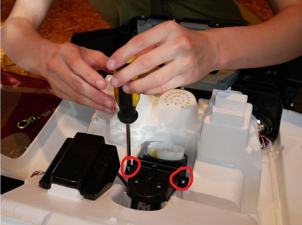
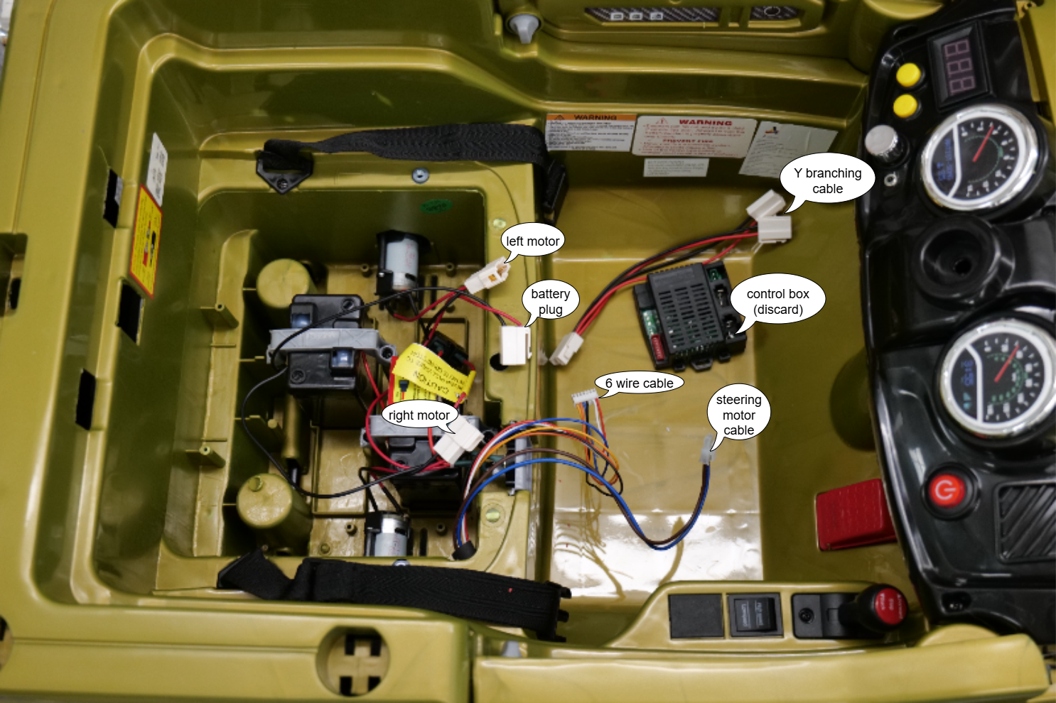
Remove the control box that came with the car. Unscrew the screw securing it and unplug all wires that are connected to it. The control box is not needed and can be discarded. Keep the Y branching cable that connects the two motors to the control box, as it will be used to connect the motors to the GBG-PCB.
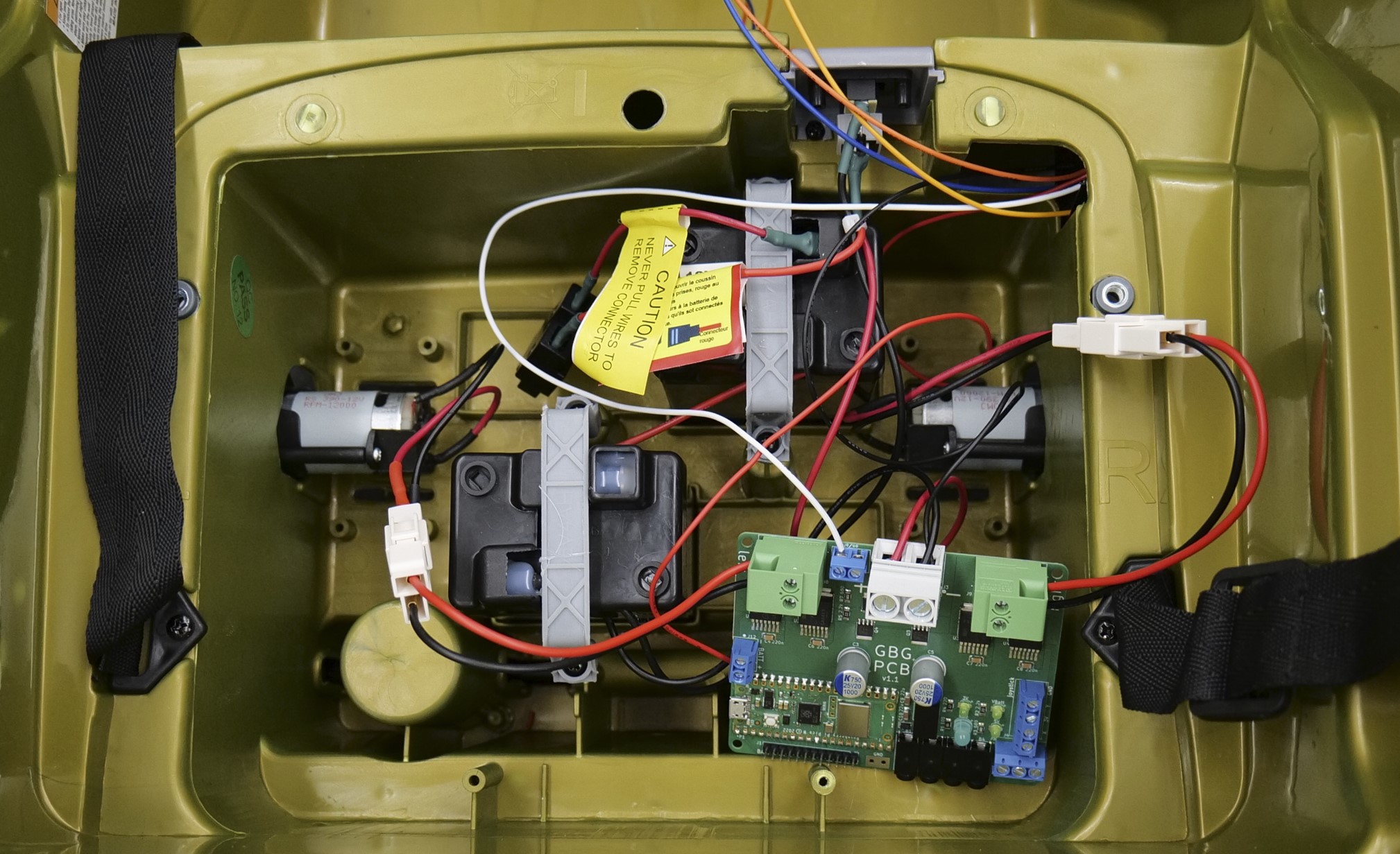
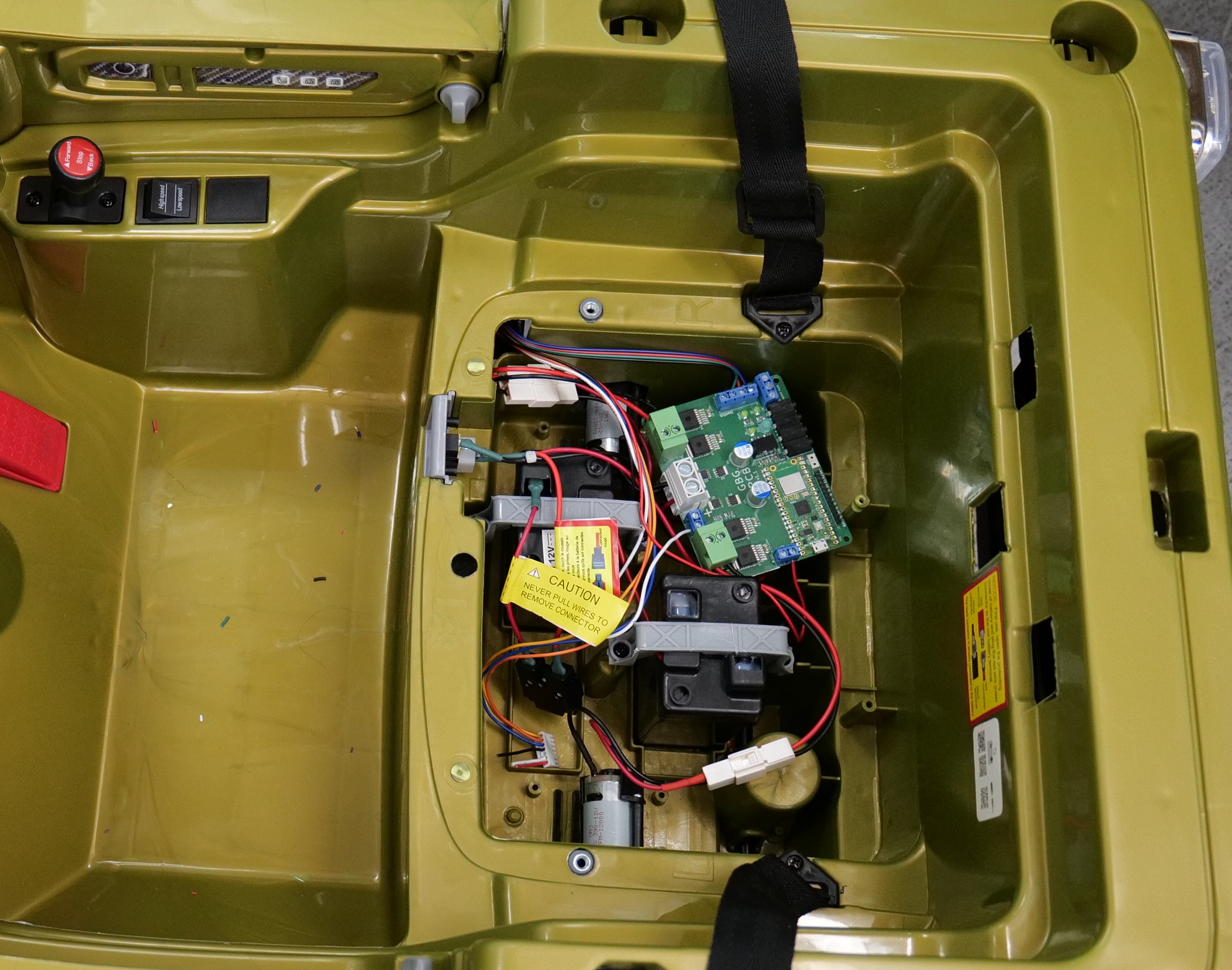
Find the left motor plug, the battery plug, the right motor plug, the 6 wire plug, the steering motor plug, and the Y branching cable that was connected to the control box. The plugs are shown in the image below.
Gently pull on the steering motor plug and discard the brown and blue steering motor wires. The other end was unplugged when you removed the steering motor. The steering motor wires are not needed. You can cut any heatshrink tubing that is around the steering motor plug or even the steering motor wires themselves, if needed, to remove the steering motor wires. Don’t cut any of the thin wires that might be bundled with the 2 steering motor wires.
Connect the PCB to the battery wires
The PCB can be left connected to the battery. It does not need a switch between itself and the battery. The PCB has MOSFETs that stop electricity from flowing when the on/off switch is off. When the PCB is off it draws practically zero current (2 nanoAmps) so it will not make the battery discharge.
Cut the red battery wire where it connects to the battery plug. Strip 3/8” (10 mm) of insulation off the end of the red wire. Connect the red battery wire to the positive large BATTERY screw terminal on the GBG-PCB (labeled “+”). Tighten the screw terminal tightly to hold the wire in place.
Cut the black battery wire where it connects to the battery plug. Strip 3/8” (10 mm) of insulation off the end of the black wire.
Cut the thin black wire off the 6 wire plug. Strip 3/8” (10 mm) of insulation off the end of the black wire.
Put both the black battery wire and the thin black wire from the 6 wire plug into the negative large BATTERY screw terminal on the GBG-PCB (labeled “-“). Tighten the screw terminal securely to hold both wires in place.
Wire the PCB to the on/off switch
Cut the thin white wire off the 6 wire plug. Strip 1/4” (6 mm) of insulation off the end of the white wire. Connect the white wire to the left side of the ON/OFF screw terminal on the GBG-PCB. It’s important that the white wire is connected to the side of the on/off switch that is closer to the left motor screw terminal. The white wire should go to the side of the on/off screw terminal that is closer to the word “off” than the word “on” where it says “on/off” on the PCB.
Cut the thin red wire off the 6 wire plug. Strip 1/4” (6 mm) of insulation off the end of the red wire. Connect the red wire to the small BATT screw terminal on the GBG-PCB (labeled “+”).
Wire the PCB to the motors
Plug the Y branching cable that was connected to the control box into the two motor plugs. Then, cut the plug where the 4 wires meet the plug.
Strip 3/8” (10 mm) of insulation off the ends of the wires.
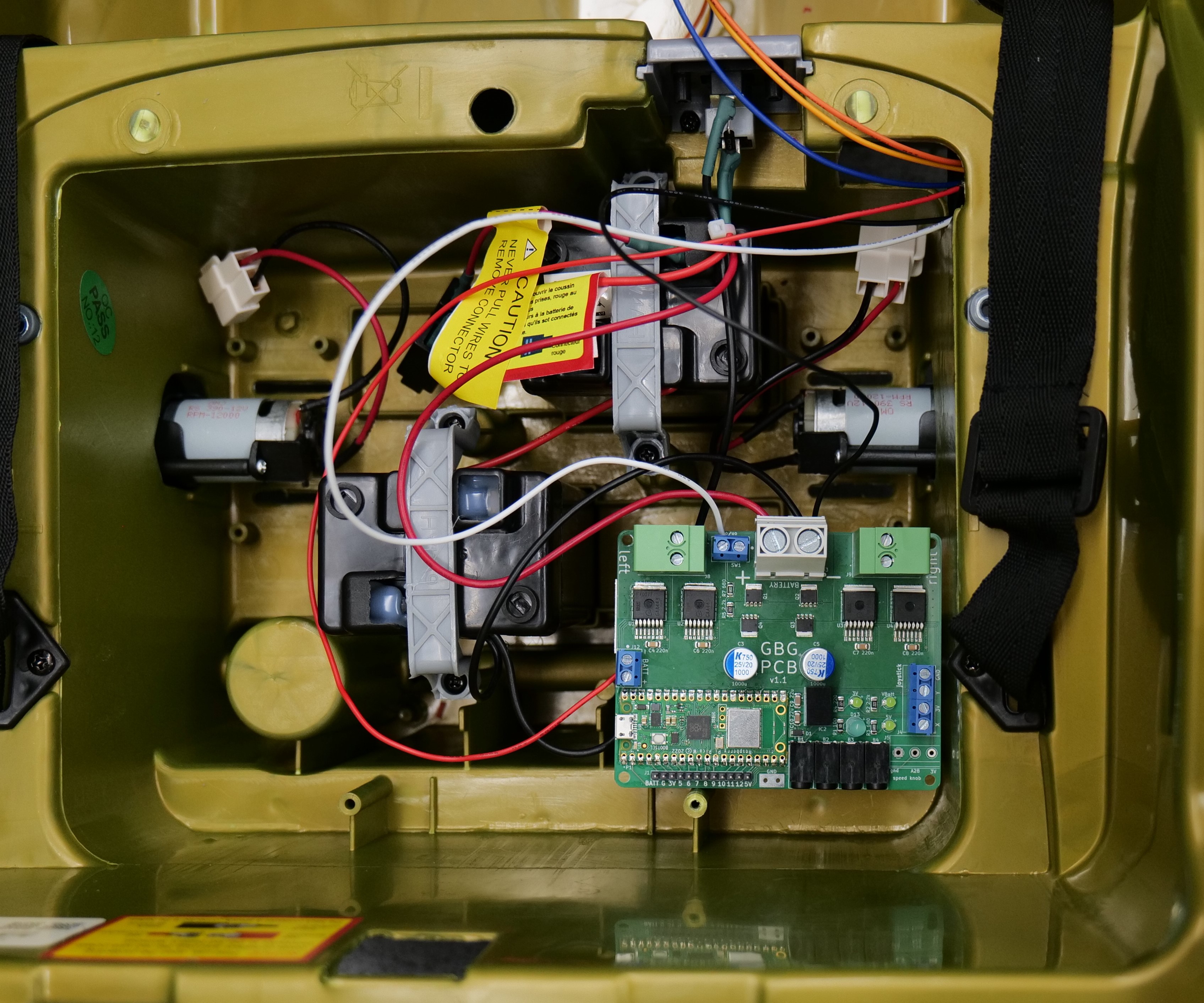
Connect the motor wires to the left and right motor screw terminals on the GBG-PCB. The red wires should go to the sides of the terminals marked with a small “+” and the black wires should go to the sides of the terminals marked with a small “-“.
Wire the Joystick
Route the joystick cable
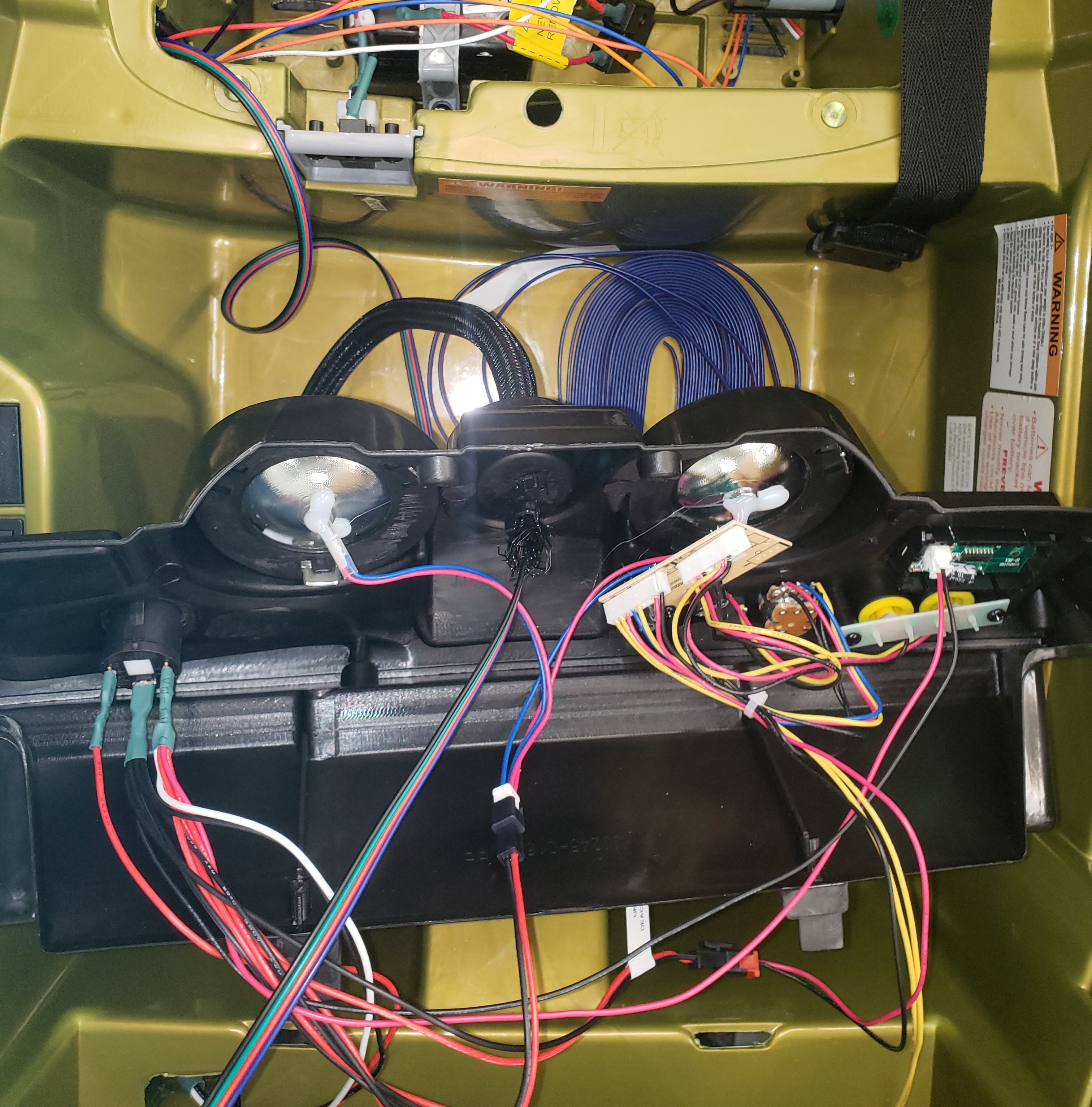
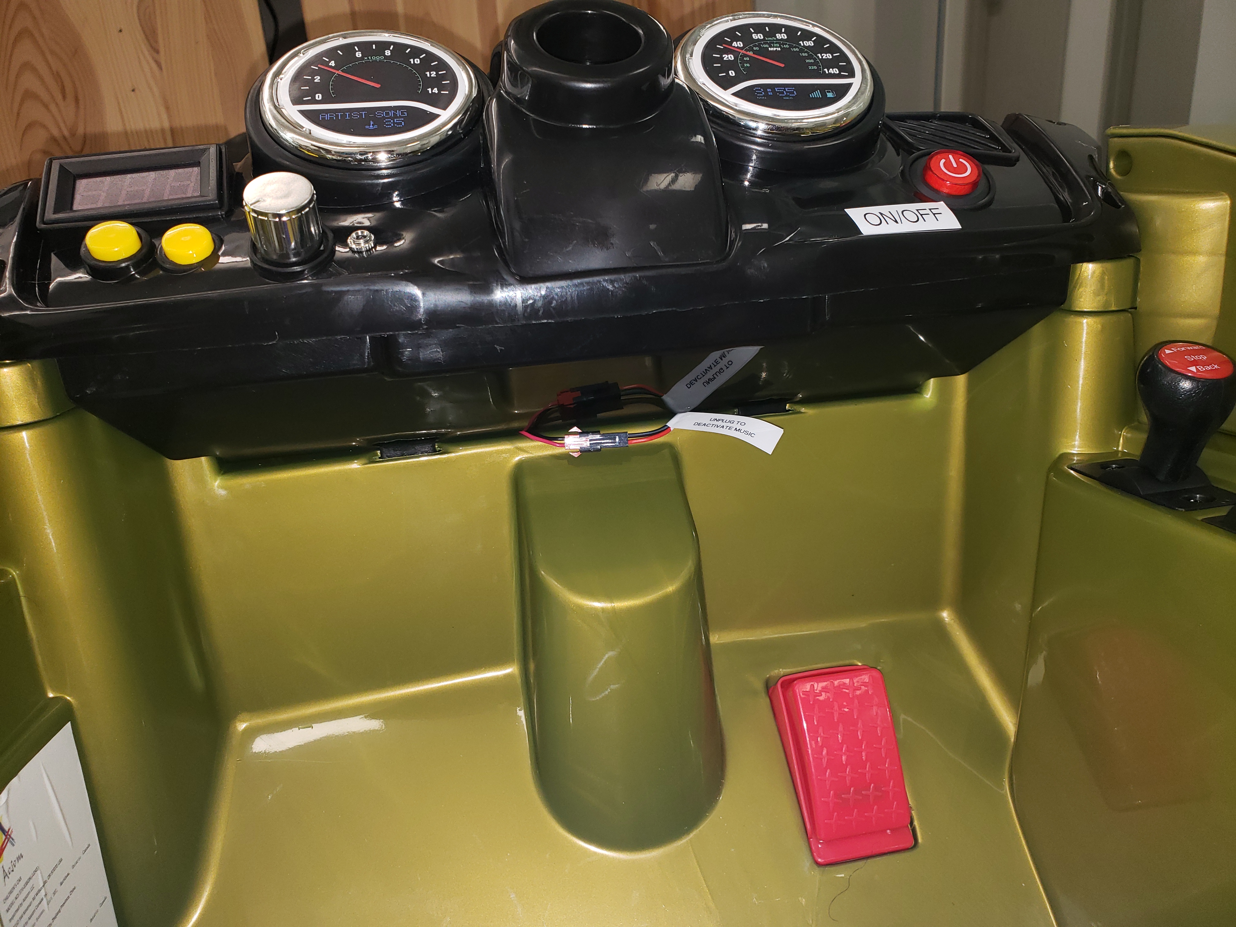
Take the 4 wire cable and put it through the hole at the front right of the battery compartment (following the wires that had gone to the 6 wire plug). The 4 wire cable should go inside the plastic guard under the gear shift lever. If you can’t push the cable through so it comes out in front of the plastic guard, you could unscrew the plastic guard, run the cable, then put the plastic guard back in place.
Unscrew the dashboard.
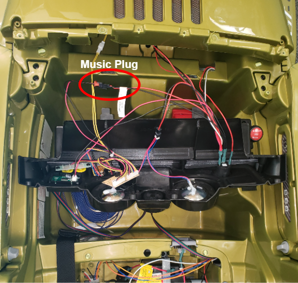
Identify the plug that powers the music and horn. Label it “UNPLUG TO DEACTIVATE MUSIC”.
Route the 4 wire cable up to the dashboard, following the red, white, and black wires that go to the dashboard. The 4 wire cable should then go out of the dashboard through the hole for the steering wheel and reach about 13 inches (33 cm) outside the dashboard.
Cut a 12 inch (30 cm) length of wire protector tubing and slide it over the length of the 4 wire cable that is outside the dashboard. This will protect the wires from being pulled by the kid.
Add a zip tie around the 4 wire cable and the wire protector tubing on the inside of the dashboard, to keep the cable from being pulled out of the dashboard.
Screw the dashboard back in place, leaving the “unplug to deactivate music” plug out of the dashboard.
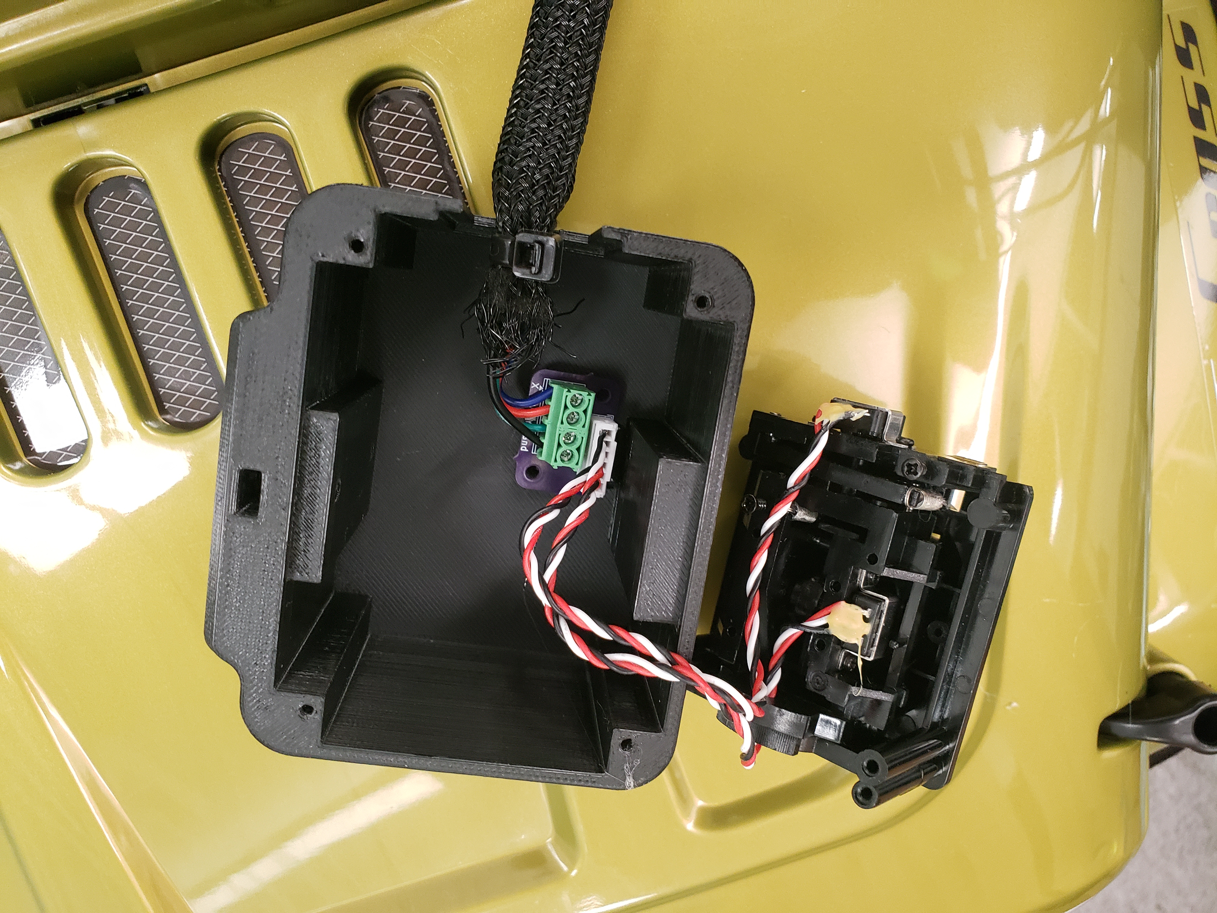
Plug the joystick into the joystick pcb.
Connect the 4 wire cable to the screw terminal on the joystick pcb. Strip 1/4” (6 mm) of insulation off the ends of the wires and connect them to the screw terminal on the joystick pcb.
Hot glue the joystick pcb inside the 3d printed joystick holder so that it can’t move around and jam the joystick. Match the position in the photo below.
Add a ziptie to the end of the wire protector, to keep the wires from being pulled out.
Before closing up the joystick holder, drop a 4-40 nut into the slot for the top hole. This nut will be used to secure the joystick holder to the pvc frame later.
Screw the top of the joystick holder to the bottom of the joystick holder, using 4 m2.2x14mm screws. If the joystick is incorrectly rotated, the 3d printed parts won’t fit together. The ziptie and wire protector should be inside the joystick holder.
At the other end of the 4 wire cable, in the space under the seat, strip 1/4” (6 mm) of insulation off the ends of the wires. Connect the wires to the screw terminal on the GBG-PCB labeled “joystick”. Make sure that between the GBG-PCB and the joystick pcb, the wires are connected in the same order. “X”, “3V”, “Y”, “GND” on the two boards should be connected together.
Attach Joystick Holder
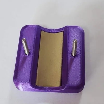
Cut a 0.75 inch (19mm) by 1.75 inch (45mm) rectangular piece of 1/16” thick rubber gasket sheet.
Put the piece of rubber into the recessed rectangle of the joystick holder clamp. (You may have to trim the piece of rubber to size)
Remove the 4-40 machine screws that are temporarily holding the 4-40 nuts in the joystick holder, taking care not to let the nuts fall out of their slots. Then slide the bolts through the two holes in the 3d printed clamp piece.
Bolt the joystick holder base to the clamp around the PVC crosspiece. It should take almost no force with the screwdriver – if you feel resistance, check the alignment of the nuts and try again. Tighten both bolts similar distances.
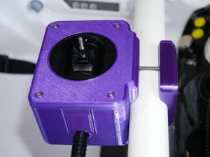
Twist the two silver metal pieces off of the joystick threaded shaft and discard.
Screw one of the 3D printed joystick handles onto the shaft of the joystick. Don’t over tighten since you’re screwing into plastic. It may help to drill out the hole with a 3/32” drill bit. Alternatively, you can use the handle models modified to use threaded heat set inserts to connect the joystick handle to the joystick shaft.
Add some hot glue where the joystick wires enter the dashboard and where the joystick wires enter the joystick holder as additional strain relief.
(optional) Wire Buttons and/or Speed Knob
Buttons
Plug up to 4 buttons into the headphone-style jacks on the GBG-PCB.
When you connect the GBG-PCB to your computer to change the settings, click the “show all” button and check the box next to “enable button ctrl”. Then, you can set what direction each button should make the car move in.
Speed Knob
You can add a knob to the car for easily adjusting the maximum speed of the car without needing to reprogram it.
Connect a potentiometer to the screw terminal labeled “speed knob”.
When you connect the GBG-PCB to your computer to change the settings, click the “show all” button and check the box next to “use speed knob”.
Reconnect the battery
The cars are sold with a red wire disconnected from the battery to keep the car from turning on during shipping. This also made it safer to work on the electrical system. Now that you’re done with the wiring, you can connect the wire to the battery.
Software and Settings
Flash the firmware to the Pico
If you got your GBG-PCB from someone who already programmed it for you, then you can skip ahead to calibrating the joystick and adjusting settings.
Go to the go baby go programmer website and follow the instructions to upload code to a new car. Select the PCB_gbg_program not the standard gbg_program.
Connect
Connect the GBG-PCB to your computer with a micro USB cable
Go to the go baby go programmer website
Follow the instructions pointed to with the magenta arrow to connect to the car
Calibrate the joystick and adjust settings
Click the “calibrate the joystick the easy way” button and follow the instructions on the screen
You can also adjust the speed and acceleration settings for the car.
Test the car
disconnect the car from the computer
turn on the car using the on/off button on the dashboard
the three green lights on the PCB should turn on
you should hear a short beep from the motors
the car should drive when you move the joystick
the blue light on the PCB should turn on when the car is moving and turn off when the joystick is centered
if the blue light blinks quickly that means the joystick needs to be left centered for a few seconds before trying to move and that the joystick may need to be recalibrated
Finishing Touches
clean up the car
Secure the GBG-PCB inside the battery compartment using hot glue (make sure the USB port can still be used).
Clean out bits of wires and insulation that might have fallen into the car or electronics compartment. Ideally, use a vacuum cleaner.
Seatbelt
Improvise, based on requests from a physical therapist.
Installing the Harness System
These instructions are for installing a “carseat” harness system. The harnesses we used in the past have become hard to find.
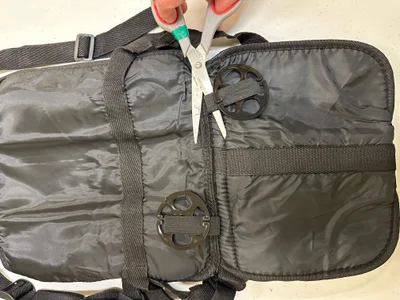
9.01 Separate the straps that connect the harness system’s head rest cushion to the seat cushion. Remove the figure-8 shaped plastic clip used to hold the loose end of the strap as well (these clips will be reinstalled later, so keep them in a safe place).
Cut the two elastic bands that hold the round plastic clips to the underside of the harness system’s seat, and dispose of the elastic and the round clips.
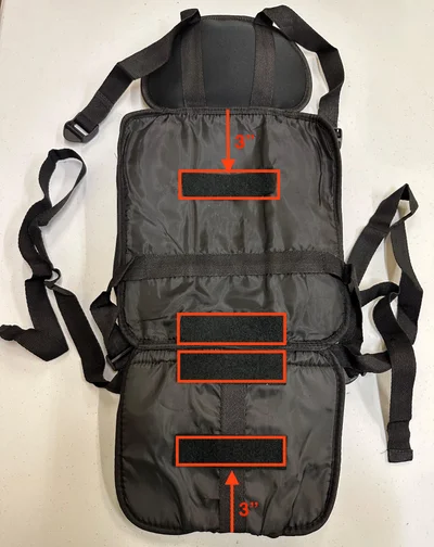
Secure (using their adhesive backing) four strips of 1 ½” x 5” velcro (the softer, loop pieces) to the back of the harness system, as outlined in red in the photo. All strips should be centered left/right on the harness, with two of them positioned on either side of the seam between the seat and the back cushions, one so that its outermost edge is 3” from the bottom edge of the harness, and one so that its outermost edge is 3” from the seam between the seatback and the headrest.
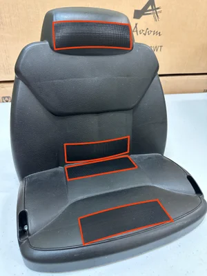
Secure (using their adhesive backing) four strips of 1 ½” x 5” velcro (the harder, hook pieces) to the Jeep seat, as outlined in red in the photo. All strips should be centered left/right on the seat, with two of them positioned just above and below the bend between the seat and the back cushions, one toward the front edge of the seat (with its front corners just touching the front seam of the seat), and one at the lower edge of the head rest (with its lower corners just touching the seam between the headrest and the seat).
9.05 Remove the screw that secures one of the seatbelt clips to the jeep’s chassis. Before removing the clip, it is helpful to use a silver Sharpie to mark a “D” ( for Driver’s side) or “P” (for Passenger side) on the clip to ensure that you do not change the orientation and location of the clip when you reinstall it in a later step.
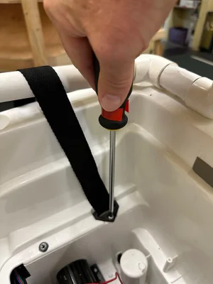
9.06. Without installing the seat yet, place the harness system approximately where it will be placed in the Jeep (as if the seat were installed). Feed the harness strap from the side of the harness seat (taking care not to allow any twists) through the seat belt clip, entering from the top (over the screw) and then routing it out from under the clip and out of the car, as in the photo.
9.07. Retighten the screw that secures the clip that secures the seatbelt strap, leaving it just loose enough that you are still able to slide the harness strap through the clip.
Repeat Steps 9.05–9.07 with the harness strap and seatbelt clip on the opposite side of the car (again making sure to avoid twists in the harness strap when it is threaded through the clip).
Slide the Jeep’s plastic seat into place, taking care to avoid having the velcro straps on the seat and harness from making contact until the seat is approximately in place. Position the harness system squarely over the seat, centered and with the seam between the seat and seat back positioned appropriately. Press the harness into the seat so that the velcro strips become secure.
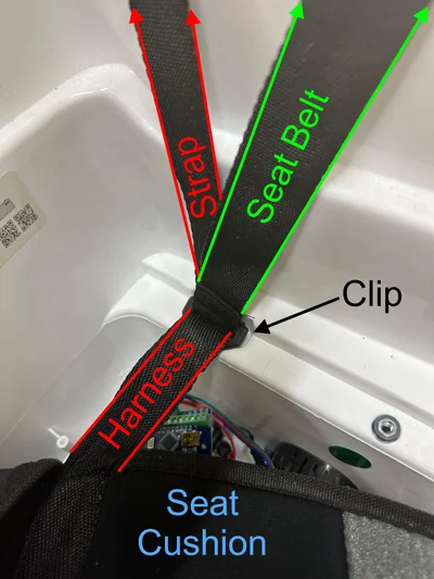
Replace the figure-8 shaped clips (which were removed in Step 9.01) onto the loose ends of the harness straps that were just threaded through the seat belt clips.
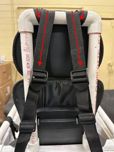
Route one of the head rest harness straps over the top PVC bar of the back rest and loop it one time around the bar as shown in the photo. Route the harness strap from the seat cushion through the plastic clip on the upper strap, then place the loose end in the figure-8 clip to secure it. Repeat this routing with the straps on the other side of the harness. Tighten both sets of straps evenly.
Secure the Jeep seat with screws found in the Jeep box.
last steps
Label the “on/off” button (the red power button on the dashboard)
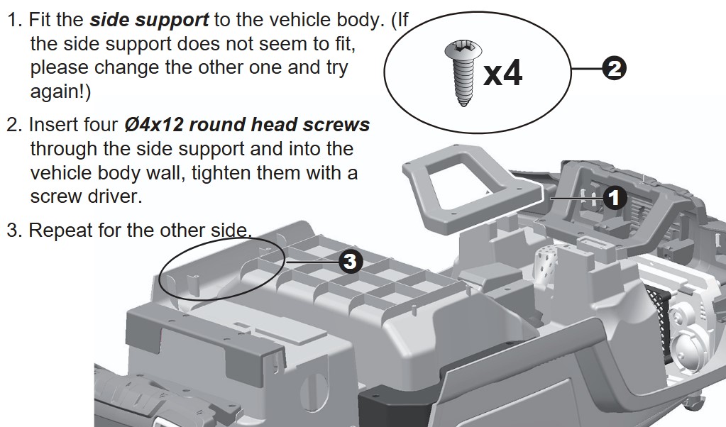
Screw the grey reinforcement pieces to the bottom of the car using screws that came with the car.
Print a user guide for the car.
Congratulations! You’re done!
Check your work
Check your work with this inspection checklist