gbg-pcb
Use a GBG-PCB to make a Zupapa bumper car controlled by a joystick without needing to solder anything.

questions? post here or email gobabygocarswithjoysticks@gmail.com
Playlist of Videos for these instructions
Parts needed
- a 12 volt Zupapa bumper car https://www.amazon.com/dp/B0CLLW3FBG?th=1
- These instructions are written specifically for this model of car. Other cars may have different circuits and require different steps. If you are using a different model, take a look at these general instructions for using this PCB. A GBG-PCB can control most cars as long as they are 12 volts.
- 3 foot length of 4 wire electrical cable
- Radiolink joystick replacement for RC controllers AT9 and AT10 (get the “back to middle” type that springs back on both axes)
-
3d printed parts
- an assembled joystickpcb (I’ll include these with any GBG-PCBs that I give out)
- an assembled GBG-PCB
v1.1 and v1.2 boards are interchangeable - they use different heatsinks as component availability changed.
- Feel free to use these files and make your own boards or modify this design. The components cost approximately $50 but it really depends on what quantity of boards you are making and what shipping costs you have to pay.
- Email gobabygocarswithjoysticks@gmail.com. I might have assembled boards to sell or donate to you. I’ll include a joystick pcb with any GBG-PCBs I give out. Boards currently in-stock: 2
- Use this PCBWay link to order fully assembled boards. Thank you to PCBWay for supporting this project. (As of May 2025 this link has not been tested - I haven’t ordered any assembled boards). When ordering assembled PCBs, you may be asked by PCBWay whether you want a Pico 1 or Pico 1W. Specify the 1W if you want wifi remote capability, or clarify that you want the Pico 1 if you don’t need a remote and want to save a couple dollars.
Tools needed
- wire strippers
- wire cutters
- small (3mm) flathead screwdriver
- large (6mm) flathead screwdriver
- small (2.0) Phillips screwdriver
- micro USB cable
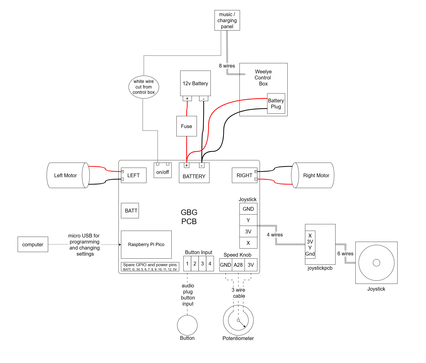
PCB Schematic
PCB List Of Components
Instructions:
Unpack the Car
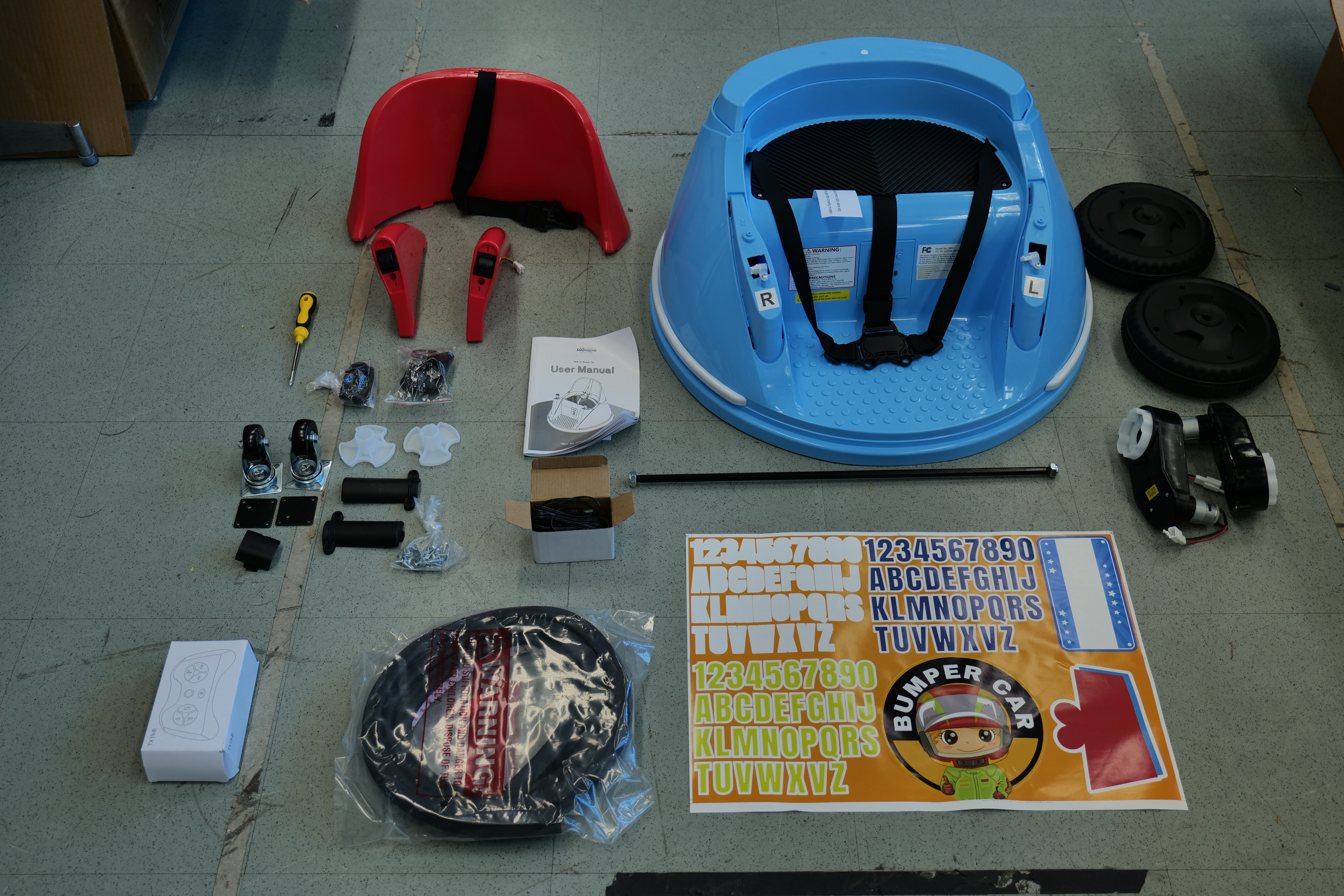
Connect Wheels
The following steps are assembly steps 1 and 2 in the Zupapa bumper car user manual “Install Car Wheels” and “Install Caster Wheels”
Assemble the axis (Zupapa calls the axel the “axis”)
On both ends of the axis add a motor, wheel, washer and nut.
Use the included wrenches to tighten the nuts. They are unusual-looking wrenches. Alternatively, if you have normal wrenches you could use them.

Make sure both nuts are fully screwed on until the axis sticks out through them by a millimeter on both ends.
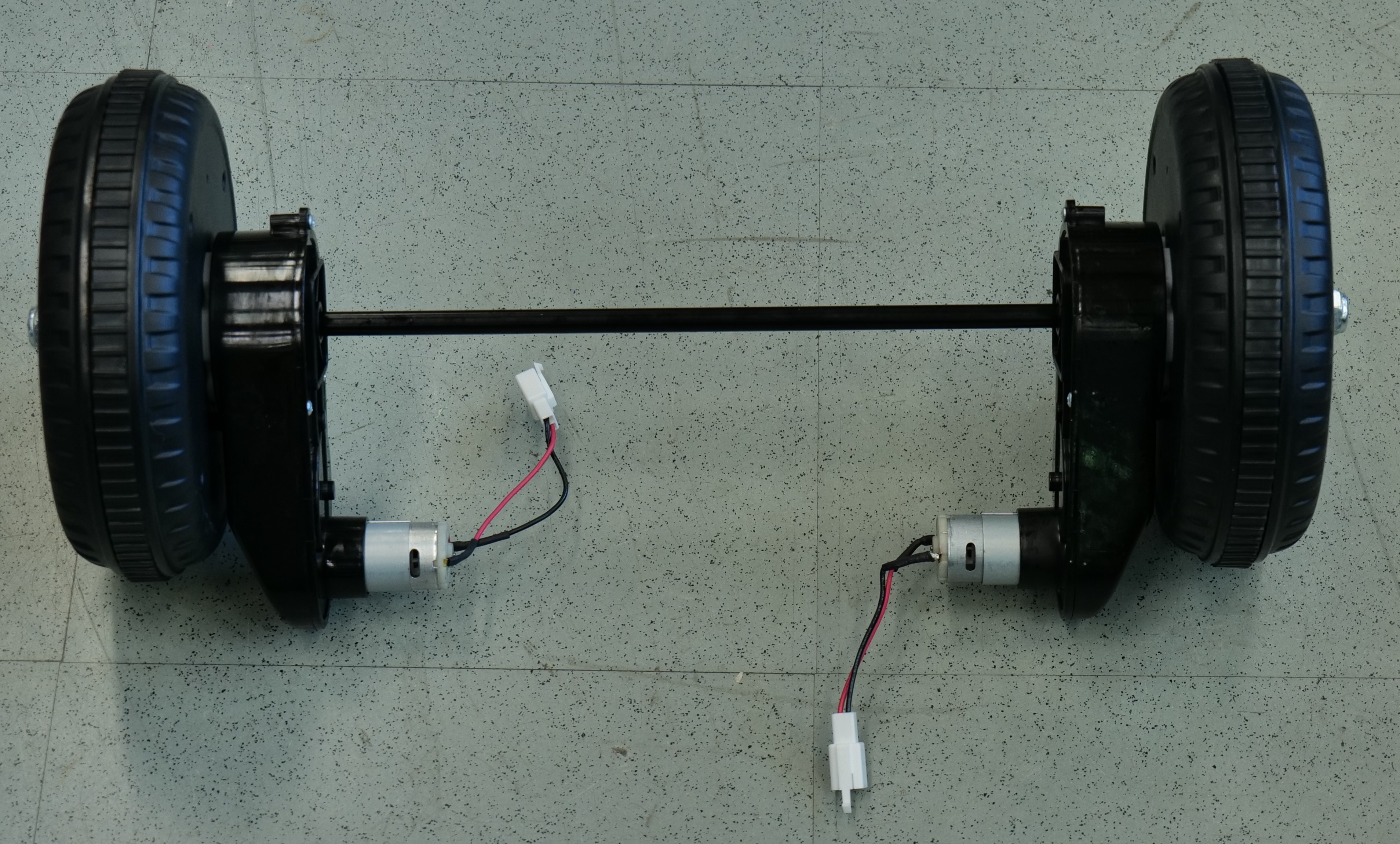
Attach the wheels
Turn the car upside down
Place the axis and wheel assembly into the bottom of the car.
Plug the two motors into the plugs
Attach the 2 plastic motor covers with 2 small-head screws each
Attach the 2 metal axis covers with 4 small-head screws each
Attach the 2 universal (AKA swivel or caster) wheels with 4 large-head screws each
Electrical Modifications
Turn the car back upright
Remove the Seat and the Battery Cover
Unscrew the 2 screws holding the seat in place and lift it off. Then, unscrew the screw on the white wire holder and the 4 screws holding the battery cover in place and remove the cover.
Disconnect the battery
It should be shipped with the red wire to the battery already disconnected. If a wire is connected to the red terminal of the battery, disconnect it to keep the car off and safe while you work on it.
Put tape over the red terminal of the battery to prevent accidental short circuits.
Connect the GBG-PCB
Connect the on/off switch wire
Find the white wire going to the 9 wire plug on the control box. Cut the white wire close to the plug.
Strip a quarter inch (6 mm) of insulation off the end of the white wire.
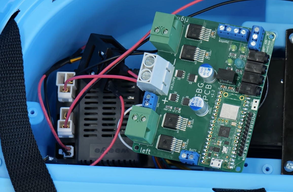
Connect the white wire to the on/off terminal closer to the left motor port.
Connect the PCB to the battery wires
The PCB can be left connected to the battery. It does not need a switch between itself and the battery. The PCB has MOSFETs that stop electricity from flowing when the on/off switch is off. When the PCB is off it draws practically zero current (2 nanoAmps) so it will not make the battery discharge.
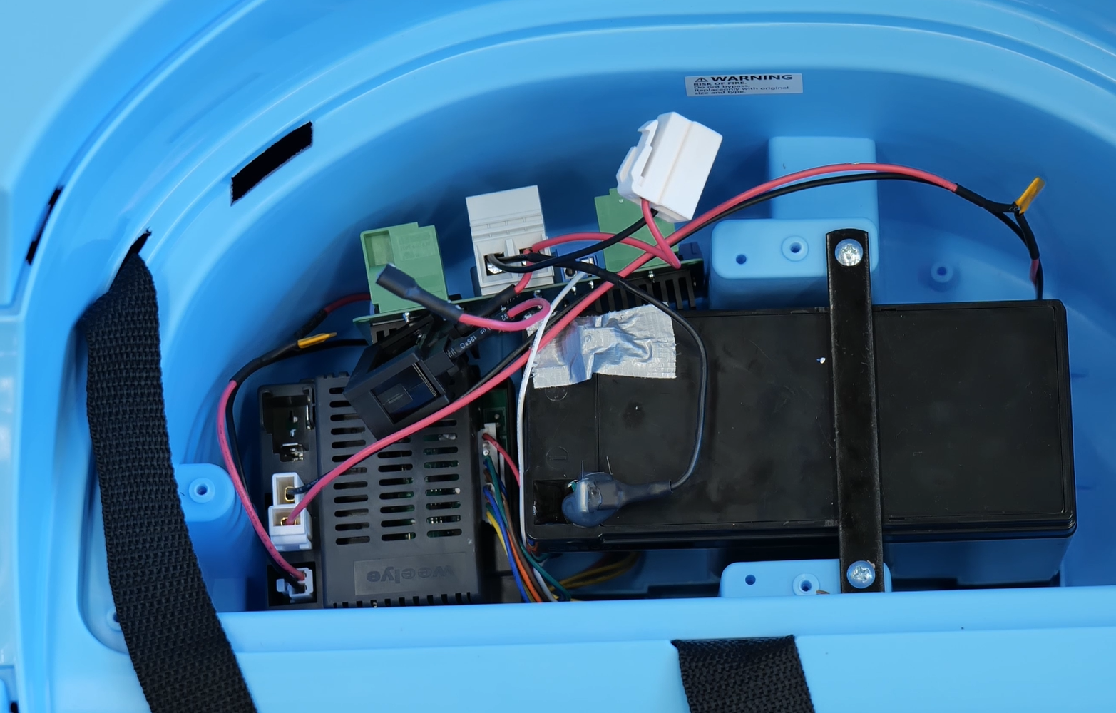
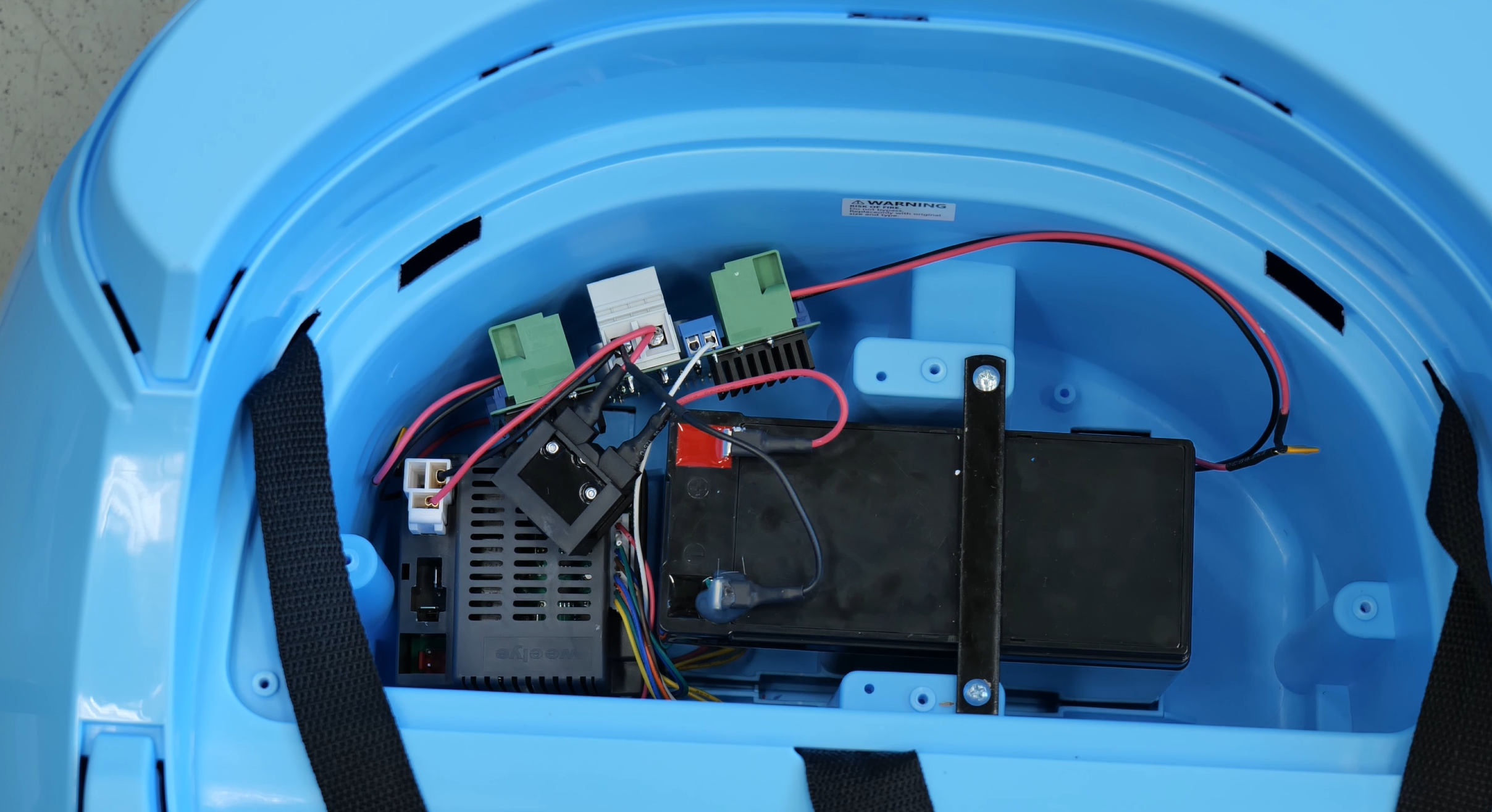
Unlike other instructions, in this car the Weelye control box that comes with the car is left in the circuit. The GBG-PCB is wired in parallel with the control box from the battery. The control box doesn’t control the motors but it does handle charging and power the control panel that does music, lights, charging, and the on/off switch.
positive battery wire
Cut the red battery wire close (within an inch) to the fuse box.
Strip 3/8” (10 mm) of insulation off both ends of the now cut red wire.
Twist the ends of the red wire back together.
Connect the wires to the positive large BATTERY screw terminal on the GBG-PCB (labeled “+”).
Tighten the screw terminal tightly to hold the wires in place.
negative battery wire
Cut the black wire so that both ends reach the GBG-PCB. To do that, cut the wire 5 inches (12.7 cm) from the battery.
Strip 3/8” (10 mm) of insulation off the ends of the now cut black wires.
Twist the ends of the black wire back together.
You can unplug the battery plug from the car’s control box to make it easier to work.
Connect the wires to the negative large BATTERY screw terminal on the GBG-PCB (labeled “-“).
Tighten the screw terminal tightly to hold the wires in place.
Cut the thin black wire off the 6 wire plug. Strip 3/8” (10 mm) of insulation off the end of the black wire.
Put both the black battery wire and the thin black wire from the 6 wire plug into the negative large BATTERY screw terminal on the GBG-PCB (labeled “-“). Tighten the screw terminal securely to hold both wires in place.
Wire the PCB to the motors
left motor
Unplug the left motor from the control box and cut the plug off the ends of the wires. Discard the plug.
Strip 3/8” (10 mm) of insulation off the ends of the two left motor wires.
Connect the red wire from the left motor to the left motor terminal labeled “+” (the terminal closer to the edge of the board).
Connect the black wire from the left motor to the left motor terminal labeled “-“ (the terminal farther from the edge of the board).
right motor
Unplug the right motor from the control box and cut the plug off the ends of the wires. Discard the plug.
Strip 3/8” (10 mm) of insulation off the ends of the two right motor wires.
Connect the red wire from the right motor to the right motor terminal labeled “-“ (the terminal farther from the edge of the board). This is reversed from the left motor
Connect the black wire from the right motor to the right motor terminal labeled “+” (the terminal closer to the edge of the board).
If you disconnected the battery plug from the control box, plug it back in.
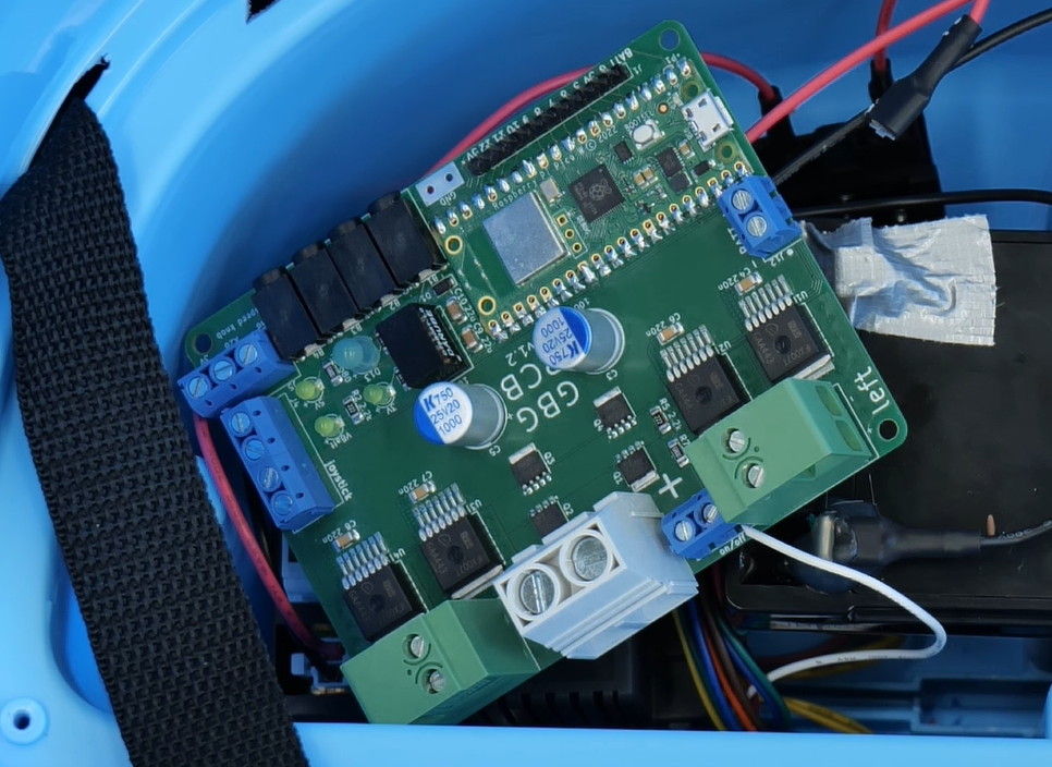
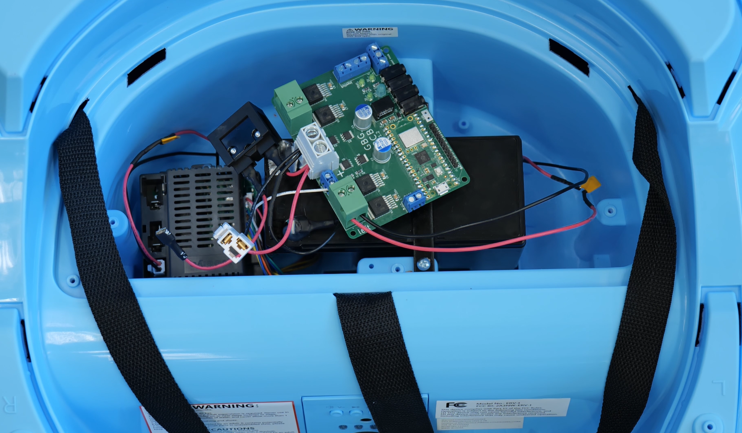
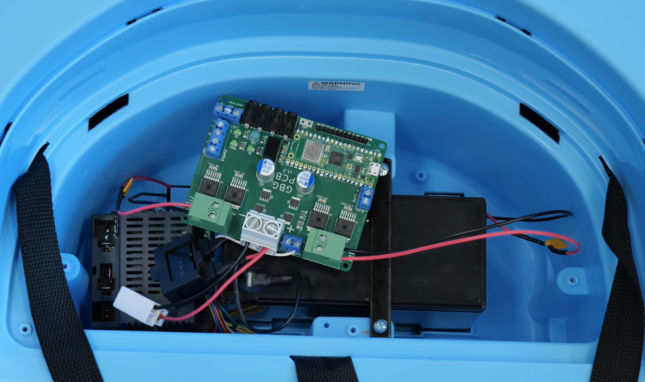
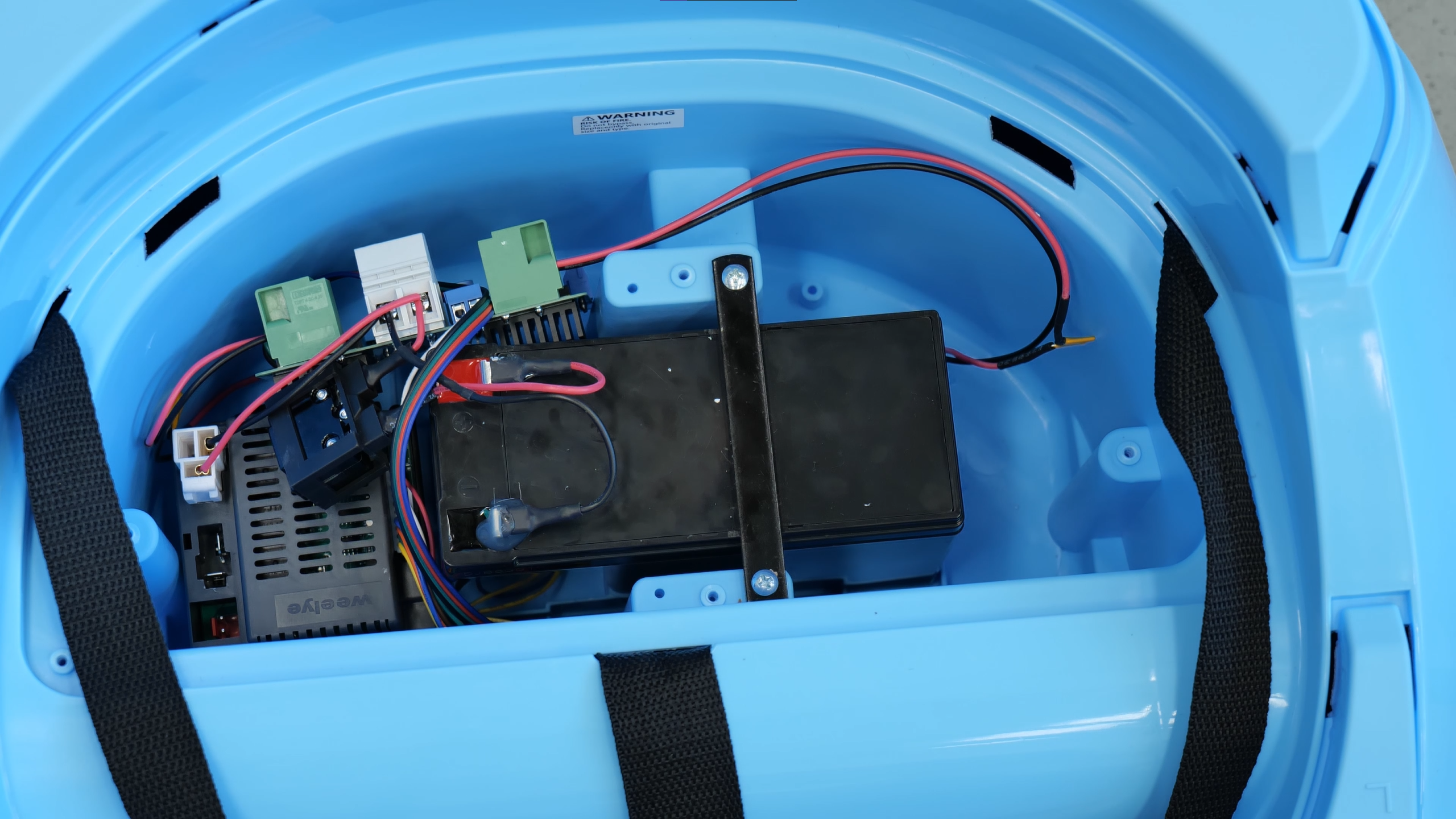
Place the GBG-PCB into the space behind the control box and the battery
Wire the joystick
Get a 3 foot (1 meter) length of 4 wire cable.
Strip 1/4” (6mm) of insulation from the 4 wires on one end of the cable.
Connect the 4 wires to the screw terminal on the GBG-PCB labeled “joystick.” The standard coloring is X=blue, 3V=red, Y=green, gnd=black.
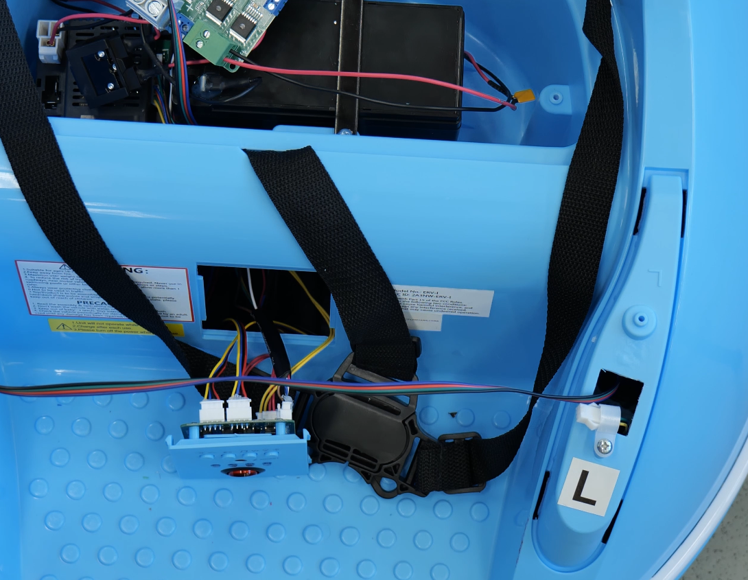
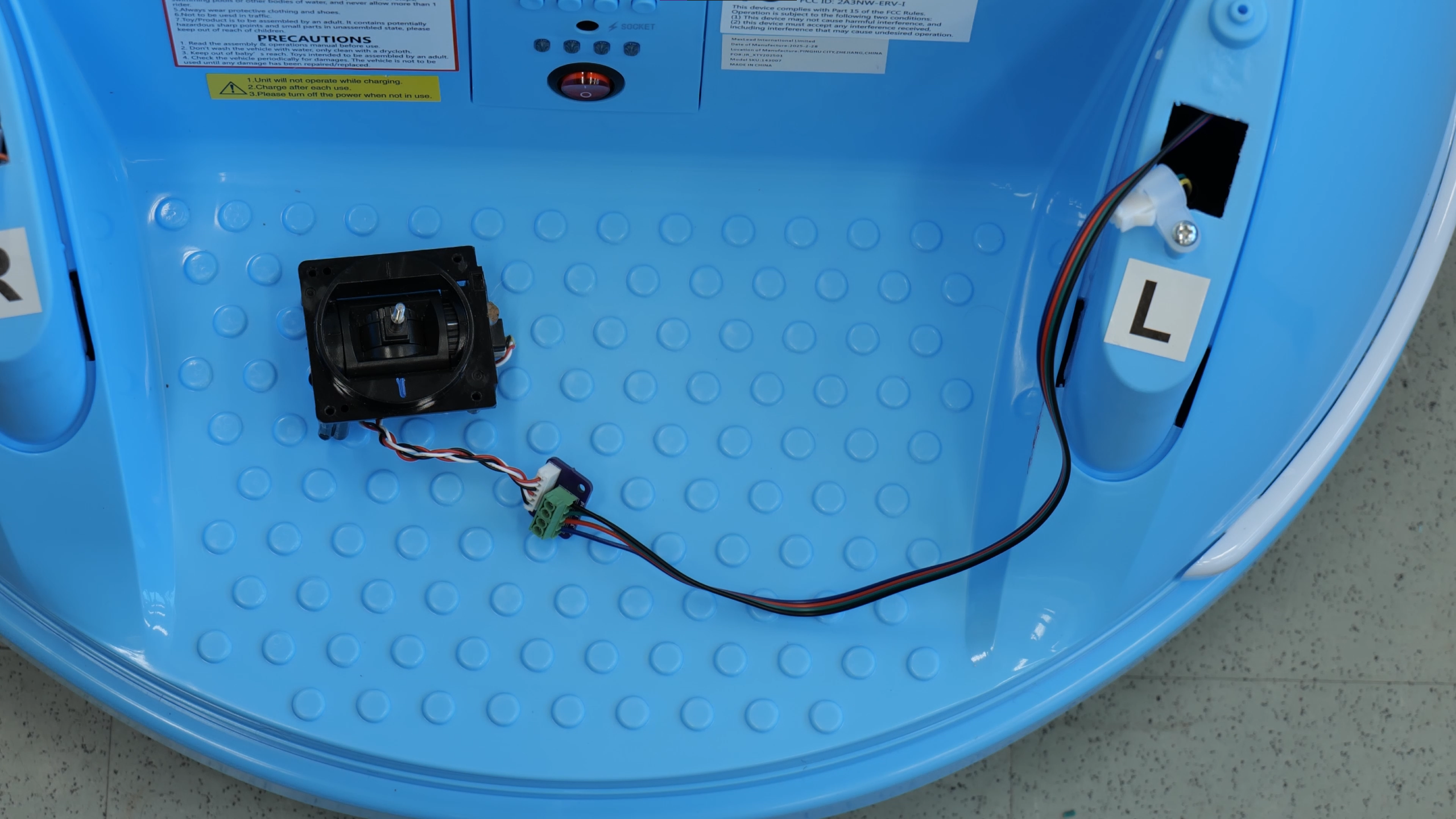
Pry the “control panel” with the charging port, music controls and red on/off switch out of the car.
Reaching through the hole where the control panel was, thread the four wire cable from the GBG-PCB up through the hole in the left armrest of the car.
Unless a kid, their family, and their doctors all agree that lights and music are ok, removing these distractions are recommended.
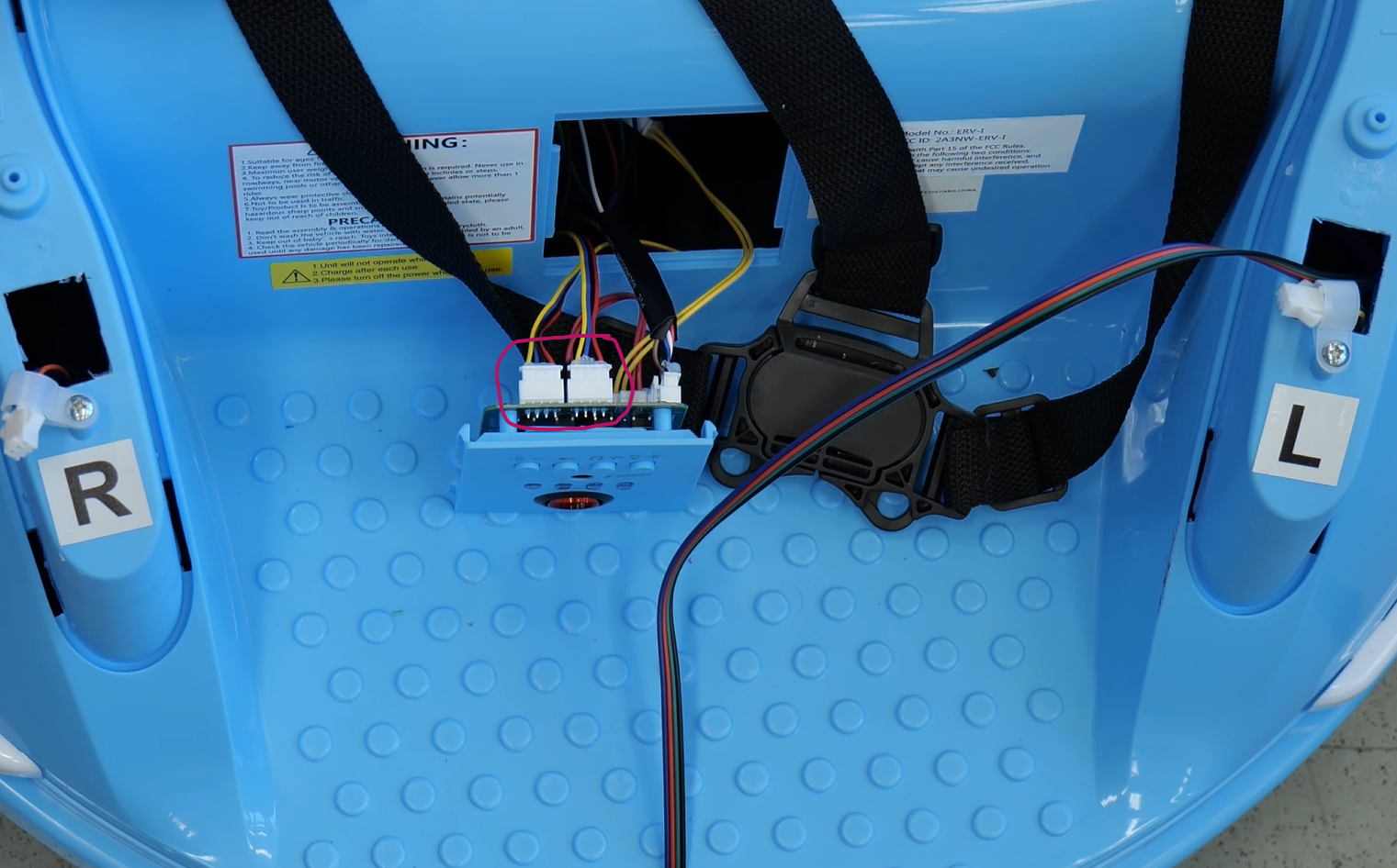
The lights can be turned off with a button on the control panel, but they turn on each time the car is turned on. The volume of the music can be changed and the music can be paused (and the car can even be a bluetooth speaker for custom music), but if the speaker is connected the car will play engine noises and then music when it is first turned on.
Unplug the two 4 wire cables from the top of the control panel to turn off the lights. The two plugs that need to be unplugged are circled in the photo.
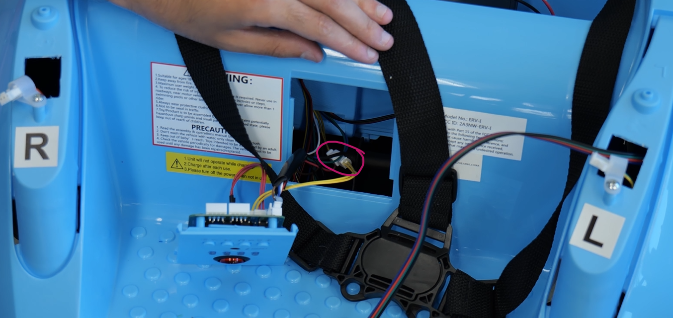
Reach into the hole where the control panel was and find the plug connecting two yellow wires together. Unplug the yellow wires to turn off the audio.
Push the control panel back into the car.
Strip 1/4” (6mm) of insulation from the 4 wires on the end of the 4 wire cable that is now sticking out of the left armrest
Connect the wires to the screw terminal on the joystick circuit board. Make sure that between the GBG-PCB and the joystick board, the wires are connected in the same order. “X”, “3V”, “Y”, “GND” on the two boards should be connected together. The standard coloring is X=blue, 3V=red, Y=green, gnd=black.
Connect the red battery wire to the battery (it plugs into the tab on the battery then locks into place).
(optional) Wire Buttons and/or Speed Knob
Buttons
Plug up to 4 buttons into the headphone-style jacks on the GBG-PCB.
When you connect the GBG-PCB to your computer to change the settings, click the “show all” button and check the box next to “enable button ctrl”. Then, you can set what direction each button should make the car move in.
Speed Knob
You can add a knob to the car for easily adjusting the maximum speed of the car without needing to reprogram it.
Connect a potentiometer to the 3 screw terminals labeled “speed knob”.
When you connect the GBG-PCB to your computer to change the settings, click the “show all” button and check the box next to “use speed knob”.
Reconnect the battery
The cars are sold with a red wire disconnected from the battery to keep the car from turning on during shipping. This also made it safer to work on the electrical system. Now that you’re done with the wiring, you can connect the wire to the battery.
Software and Settings
Flash the firmware to the Pico
If you got your GBG-PCB from someone who already programmed it for you, then you can skip ahead to Connecting to the car
Go to the go baby go programmer website and follow the instructions to upload code to a new car. Select the PCB_gbg_program not the standard gbg_program.
Connecting to the car
Connect the GBG-PCB to your computer with a micro USB cable
video of connecting the usb cable
Go to the go baby go programmer website
Follow the instructions pointed to with the magenta arrow to connect to the car
Calibrate the joystick and adjust settings
Click the “calibrate the joystick the easy way” button and follow the instructions on the screen
You can also adjust the speed and acceleration settings for the car.
Test the car
disconnect the car from the computer
turn on the car using the on/off button on the dashboard
the three green lights on the PCB should turn on
you should hear a short beep from the motors
the car should drive when you move the joystick
the blue light on the PCB should turn on when the car is moving and turn off when the joystick is centered
if the blue light blinks quickly that means the joystick needs to be left centered for a few seconds before trying to move and that the joystick may need to be recalibrated
joystick holder
// TODO
joystick handles
Twist the two silver metal pieces off of the joystick threaded shaft and discard.
Screw one of the 3D printed joystick handles onto the shaft of the joystick. Don’t over tighten since you’re screwing into plastic. It may help to drill out the hole with a 3/32” drill bit. Alternatively, you can use the handle models modified to use threaded heat set inserts to connect the joystick handle to the joystick shaft.
seatbelt and backrest
// TODO
last steps
Print a user guide for the car.
Label the “on/off” button (the red switch on the control panel)
Congratulations! You’re done!
Check your work
Check your work with this inspection checklist